
March 2016, Vol. 71, No. 3
Features
Challenges Of Relocating Large Water Mains For Rail System Expansion
Make Way For Progress
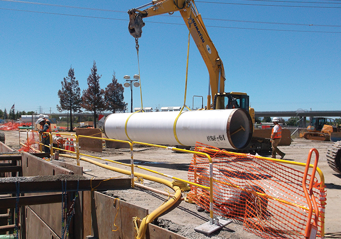
On Feb. 7, the city of Santa Clara celebrated a major milestone when it hosted Super Bowl 50 at the state-of the-art Levi’s stadium, home of the San Francisco 49ers. Next year, the city will celebrate another milestone with the completion of the 10-mile Berryessa Extension, the first phase of Bay Area Rapid Transit’s commuter rail extension south to San Jose, thanks to Santa Clara Valley Transportation Authority’s (VTA) vision.
As part of the Berryessa Extension, several new stations were proposed. Two of the new stations impacted large diameter water pipelines owned by the Santa Clara Valley Water District (SCVWD). The existing lines had to be relocated away from the new stations.
The technical design aspects of installing new pipe and fittings into an existing 66-inch concrete pressure pipe raw water main and into an existing 42-inch steel pipe treated water main are quite challenging in order to properly relocate both lines. One key consideration in this modification to the existing lines is the thrust forces generated from the realignment. The thrust restraint of the old 66-inch line posed a number of challenges since the original pipe in this area did not have longitudinal thrust forces. Additionally, the owner, the Santa Clara Valley Water District, had its own specialized thrust restraint procedure that was based on a 1960s paper.
The rail expansion project, which included the pipeline relocations, was awarded as a design-build contract to the joint-venture construction team of Skanska Shimmick Herzog (SSH) who teamed with Lockwood, Andrews and Newnam Inc. (LAN) and TY Lin International as their project designers.
It was quickly decided by the design-build team that it would be easier to simply relocate these water lines rather than find other sites for the new stations. A local San Jose firm, HMH Engineers (HMH), was named as the lead engineer for this relocation effort, who in turn asked LAN to assist with the large diameter design issues. HMH provided the pipeline design and agency interface while LAN provided the pipe design calculations.
A number of factors made this project more challenging than expected. First, the SCVWD had limited experience with design-build projects on its facilities. With the critical nature of the SCVWD pipelines to the county’s water supply, the cut-over times to tie-in both relocated pipelines to the existing pipelines were limited to 10 calendar days each, and there were very limited tie-in windows. Finally, due to the size of the lines and their critical nature, SCVWD’s pipelines were not often relocated and the agency demanded a cautious, robust and long time-horizon approach to relocation.
Existing water lines
The two existing SCVWD pipelines to have sections relocated were the 66-inch Central Pipeline, constructed in 1964-65, and the 42-inch Milpitas Pipeline constructed in 1992. Fortunately for the design team, SCVWD kept excellent records and was able to provide HMH/LAN with original plans, line layouts and as-built drawings for these two pipelines.
The first technical challenge was determining the existing pipe material utilized on the 66-inch central pipeline in the relocation area, as three different pipe materials were provided for this line according to the historical information. These three materials were:
- Embedded cylinder prestressed concrete cylinder pipe (PCCP) designed in accordance with the original project specifications and the AWWA C301 standard that was current at that time;
- Modified prestressed pipe (also referred to as concrete cylinder pipe (CCP)) that American Pipe and Construction (now NOV-Ameron) designed in accordance with the original project specifications and Federal Specification SS-P-381A. Today we refer to this product as concrete pressure pipe, bar-wrapped, steel-cylinder type per AWWA C303; and
- Welded steel pipe with cement mortar lining and cement mortar coating and a rod wrap over the steel cylinder. This was a hybrid product, part steel pipe per API 5LX with bar wrapping, cement mortar lining and cement mortar coating similar to SS-P-381A.
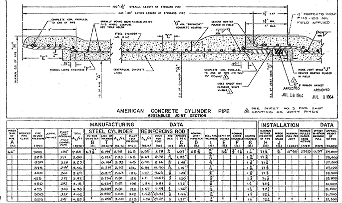
Upon closer examination of the pipeline documentation, the design team determined the pipe material was made of CCP. Figure 1 presents the joint cross section and the design of the existing pipe.
The line layout drawings for the 66-inch CCP showed the pipeline areas that contained restrained joints for thrust restraint along with areas where push-on, rubber-gasketed, Carnegie-style bell and spigot joints were utilized. In the area of the proposed relocation, only the rubber-gasketed 66-inch CCP was installed, meaning that the relocation design would have to address thrust issues that would arise from the relocation.
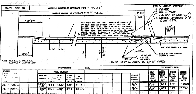
SCVWD’s records for the 42-inch Milpitas Pipeline clearly indicated it was constructed with cement mortar lined and tape coated steel pipe. As can easily be seen in Figure 2, the existing 42-inch diameter pipe operated at high pressure. Furthermore, per SCVWD standard design philosophy for reliability and protection of the public water supply, the field joints were all bell and spigot welded lap joints. Because a fully welded steel pipeline provides restraint against movement due to thrust forces, the relocation of this 42-inch pipe was thought to be much less of a design problem.
Relocated water lines
SCVWD required that the new relocated pipe be steel pipe and not PCCP or CCP. This was the best option to minimize future maintenance and risk to adjacent facilities and to water pipeline function. Furthermore, all field joints were specified to be welded, utilizing bell and spigot lap joints. Because elbows would require realigning the existing pipe to accommodate construction of the stations, it was decided that the design and pipe installation would be much simpler and cleaner with welded restrained joints. Finally, SCVWD required that the steel pipe have the same type of coating as the existing pipe. This would simplify corrosion control and minimize corrosion risks to both the new and old pipe. Therefore, the 66-inch pipe would have cement mortar coating and the 42-inch pipe would have tape coating.
Thrust restraint for steel pipe is typically accomplished in accordance with AWWA M11 along with any owner supplemental design requirements. Thrust restraint for CCP is now accomplished utilizing AWWA M9, third edition for concrete pressure pipe. This relatively new (2008) design procedure is gaining acceptance with designers and owners in the United States. However, some designers and owners prefer to utilize the older, second edition of M9 (1995) as it is a much simpler design procedure.
SCVWD had their own unique thrust restraint design procedure that is based on a paper written in 1963 by James M. Gere, a professor at Stanford University. The overall premise of the paper resembles the current M9 design procedure; that is, it utilizes frictional forces along the axis of the pipe as well as lateral displacement due to the angular change at a bend. This lateral displacement is greatest at the point of intersection of the elbow and diminishes as the length of pipe from the elbow increases. Figure 3 is from the original Gere paper, showing the length of pipe that undergoes lateral displacement, denoted as bL. Where the pipe undergoes both lateral and longitudinal displacement (the bL length), the cylinder thickness in concrete pressure pipe must often be increased to withstand these combined stresses. The total “tension anchorage” length for longitudinal displacement is denoted as L.
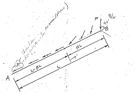
There are a few inherent flaws in the Gere paper that SCVWD has addressed in their own internal design manual, portions of which were shared with the design team. However, when the deflection angle is small, such as 30 degrees or less, the calculated lateral displacement length (bL) may be longer than the total tension anchorage length (L) (based on the initial guess of b=1 when following the design procedure). When this design flaw occurs, the SCVWD procedure is to artificially increase L by 1.55.
The thrust design of the 42-inch steel pipe was straight forward. First the design was accomplished in accordance with AWWA M11. A second design was then performed in accordance with AWWA M9 third edition, in order to combine stresses in the pipe, similar to the Gere methodology. Following is the technical memo conclusion written for the 42-inch thrust design on this project:
“The tension zones should be designated based on Method 2 lengths. This method addresses the additive effect of bending and shear to the axial loads on the pipe, which the District is requiring. However, because every joint is still a single welded lap joint, there is no impact to the overall project.”
Different thrust design
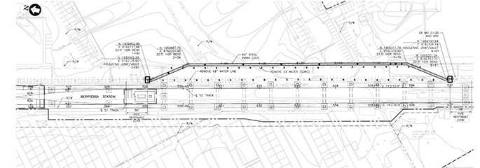
The thrust restraint design for the existing 66-inch CCP required a different process. CCP has a much thinner cylinder than steel pipe, as the bar wrap accounts for much of the total steel area required in the hoop direction. However, the bar wrap steel area does not participate in resisting the longitudinal forces related to thrust restraint. Preliminary designs demonstrated that the steel cylinder and the joint ring attachment to the steel cylinder in the old existing 66-inch CCP were adequate for the thrust force generated by the 22.5 degree elbows involved for the relocation (see Figure 4 for new layout). Initial designs required installation of 45 degree elbows, but both SCVWD and the designers agreed that a smaller angle would lessen the thrust forces.
To be conservative, LAN decided to review the thrust restraint requirements for the CCP based on the following three methods:
Method 1, AWWA M9, 2nd Edition;
Method 2, Gere as modified by the SCVWD Design Manual; and
Method 3, AWWA M9, 3rd Edition.
Method 1 resulted in a restrained joint length of 53 feet on each side of the elbow point of intersection (PI). Method 2 required restrained joint lengths of 59 feet on each side of the PI, but only after the original L was multiplied by 1.55 (as previously discussed). Method 3 resulted in a restrained joint length of 51 feet on each side of the PI. Similar to the 42-inch design, a technical memorandum was written for the 66-inch thrust design, with the conclusion as follows:
“It appears that Method 3, per the current AWWA M9 manual is the proper thrust methodology to follow for designing this project. This method properly incorporates small angles into the design procedure while the Gere methodology is limited. In addition, the latest version of M9 addresses the bending and shear stresses along with soil properties in the design where the older version (2nd edition) of M9 is silent on these subjects.
The new steel pipe 22.5 degree elbows may be supplied as part of a longer length of pipe (as compared to elbows for bar wrapped steel cylinder pipe or PCCP). If the “tie in” leg is longer than 16 feet from the elbow point of intersection (PI), then no other old bar wrapped steel cylinder pipe joints would need to be field welded as the restrained length would be 16+ feet due to the elbow leg length plus 40 feet for the first piece of bar wrapped steel cylinder pipe totaling the required 56 feet. If the new elbow leg length is less than 16 feet, one additional old bar wrapped steel cylinder joint would need to be welded.”
Concurrent with the design team’s efforts, SCVWD performed their own calculations and arrived at a length of 130 feet. LAN then tried to match the 130-foot length by using differing assumptions. The closest LAN result was a length of 112 feet assuming a high ground water table. However, the original pipelines and the current soils report did not show or reflect a ground water table above the pipe. Practically, the differences in thrust restraint lengths between the two designs resulted in the need to weld only a couple of joints of the existing 66-inch CCP on either end of the relocation. Knowing that further calculation exchanges between the design team and SCVWD would only delay the pipe approval process, and considering this pipe relocation project was on the critical path for the overall BART extension, the design-build team decided to use the SCVWD calculated 130-foot length on the existing 66-inch pipe.
Lessons learned
There were many lessons learned from this design-build pipe relocation effort. Among the chief lessons are:
When performing engineering on design-build projects, make sure the design team has all of the agencies specifications and/or design manuals. Finding out about agency design standards and manuals after submitting designs for approval causes delays and wasted effort;
The use of design-build and the compressed design and construction processes did result in relocation of the two pipelines in much less time than SCVWD normally sees. Furthermore, this accelerated process did impact the quality of the contract documents with more issues that needed to be resolved during construction, and not all to what SCVWD would have wanted; and
Addition of an experienced pipeline design and construction subject matter expert to serve as VTA/SCVWD liaison on the pipeline relocations improved the design and construction process and helped ensure the best possible schedule outcome.
ABOUT THE AUTHOR:
Robert Card, P.E, is a Senior Associate and Team Leader as well as the Chief Pipe Engineer at Lockwood, Andrews & Newnam, Inc. (LAN), a planning, engineering and program management firm. He can be reached at RJCard@lan-inc.com.

Comments