
July 2024 Vol. 79 No. 7
Features
Emergency rehabilitation brings back Baltimore’s Back River outfall interceptor
(UI) — The Back River Outfall Interceptor (BROI) is a 132-inch-by-147-inch inside-diameter, arched interceptor. Built in 1907, the shallow conduit was constructed of unreinforced concrete with a brick lining at the lower third.
It required emergency repair after discovering severe damage and, in some areas, full deterioration. This was due to two 30-inch force mains (easterly and westerly) entering into the BROI at the crown, where a sinkhole from a failed manhole had developed.
“It was a prime example of what happens when H2S eats up concrete,” said Linda Cassel, project manager, Boyer Inc. of Houston.
Ulliman Schutte Construction LLC (USC), Miamisburg, Ohio, was the general contractor and Boyer was the subcontractor called in to respond to the emergency, providing engineering and installing its Danby PVC lining.
It was the second time the two companies worked on BROI. In 2019, Boyer used its Danby liner to repair and reinforce a 333-linear-foot damaged section for USC’s construction work on the Back River Wastewater Treatment Plant Headworks Facility. So, the city of Baltimore was also familiar with Boyer’s engineering and Danby system.
The new contract was originally for 1,000 linear feet of the BRIO, underneath five-to-six lanes of Interstate 695, power lines, a parking lot and commercial property, including a mall with eating establishments. Later, the project was extended to include a 522-linear-foot section under the Norfolk Southern railroad.
Preparation for rehab
The original contract also called for a major bypass in order to gain access for the rehabilitation. Instead, USC and Boyer collaborated on an alternative.
“The objective was always to keep the interceptor in service,” said Steven Walsh, USC project manager. “We wanted to come up with a way to do that without the pain and expense of bypass pumping.”
Conceptualized by USC and designed by Boyer, the solution was a USC-constructed structure that would divert approximately 137 million gallons per day (maximum) of flow from the BROI to a parallel relief sewer and to the Back River Wastewater Treatment Plant during the rehabilitation. In 1968, an original section was abandoned after a new, 683-linear-foot reinforced section was constructed parallel to it, in preparation for the I-695 Beltway being constructed over the top.
“We figured we could take advantage of gravity, versus bypass pumping, and there was already a parallel relief structure in the area, so why not use it,” Walsh explained.
“Temporary, removable stop logs were then installed, and later removed, allowing the flow to be reestablished during wet weather events and preventing raw sewage from over-toppling the stop logs,” he added.
In addition, the two vent chambers that fed the two force mains had to be vertically extended prior to USC diverting their flow to the relief sewer.
“Each vent chamber had to be analyzed hydraulically to ensure the wastewater being released had enough volume to rise approximately 6 feet and then flow horizontally, via gravity, about 100 feet to a new inlet chamber, without stalling out due to excessive friction,” said Bill Grubbs, P.E., engineering manager, Boyer. “Virtually every edge, corner, pipe opening, valve orifice, or pipe-wall had to be accounted for, so calculations could be made to determine how high the vent structures had to be built.
“If they were built too high, they had the risk of being structurally inadequate and toppling over. If they were not high enough, the wastewater would not have enough energy to flow the required distance and would simply stall-out, likely surcharging onto the ground at the vent chambers.”
Prior to any personnel entering into the BROI, ventilation was established by installing both upstream and downstream ventilation points to pull air through the total 1,522 feet of interceptor.
“For the downstream ventilation, we used the deteriorated section of the BROI, where the easterly 30-inch force main entered it, by saw-cutting an 8-foot by 10-foot opening and installing a steel manhole form,” said Cassel.
The upstream ventilation, however, experienced some delays.
“Everything had to be coordinated with Norfolk Southern, to ensure approvals and permits were secured and all details were scheduled before crossing the railroad tracks,” said Cassel.
Once access was granted, the upstream ventilation was established at a manhole to be abandoned. “Again, this was done by saw-cutting an opening and installing a steel form for the ventilation blower,” she explained.
Boyer later lined the two force main manhole structures and lids with the Danby product, providing corrosion protection. The owner decided to abandon the upstream manhole, so Boyer lined through it, poured the structural grout and backfilled according to the approved plans.
Once the diversion structure was established, heavy debris removal and cleaning were required prior to starting the rehabilitation.
“We removed 114 tons of silt and concrete debris, then hydro-blasted the existing host pipe with 8,000 to 10,000 psi water pressure to remove all latencies and oils,” said Cassel.
Seeing is believing
“As soon as we could do a walkthrough, we saw the deterioration firsthand,” said Cassel. “The damage to the crown was significant; not a surprise, but it certainly had a ‘wow’ factor.”
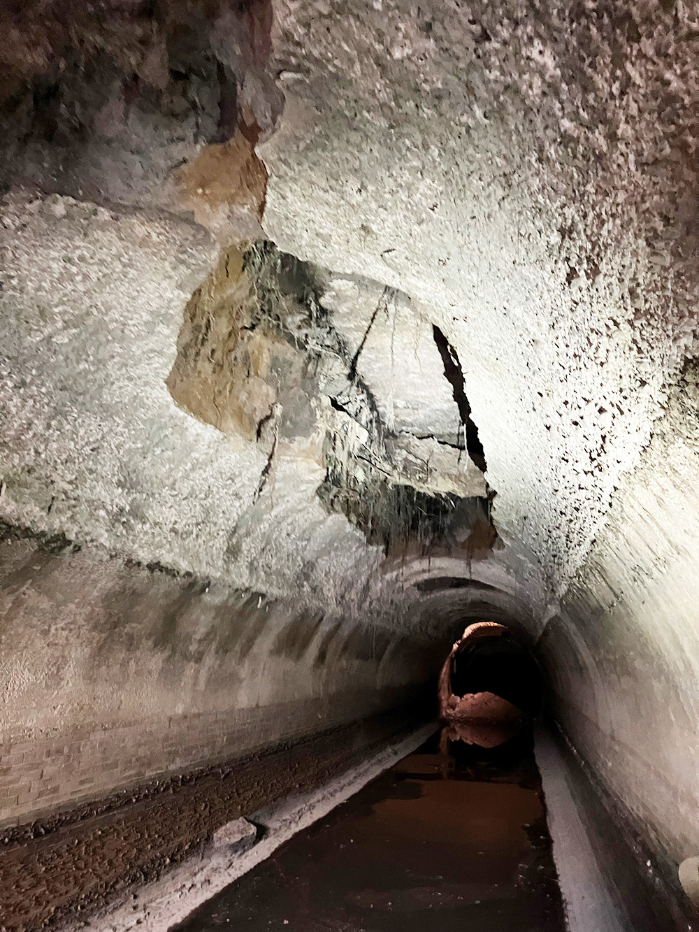
CCTV and 3D laser (LiDAR) scans gave a more-accurate picture. “LiDAR revealed a crack approximately 56 linear feet long that was visible in the side and crown,” said Walsh. “It also showed that the bottom two corners had failed and uncovered more-severe structural damage upstream.”
“The city was so impressed with the LiDAR scans and the level of detail, that we were asked to provide a PowerPoint presentation that the city could show to the entire wastewater department, to encourage more use of LiDAR,” Cassel.
Boyer was also wowed by the craftsmanship evident in the 1907 interceptor. “The hand-laid brick on the bottom third was perfect,” said Grubbs. “Not one brick was out of place.”
“It’s overwhelming that the basic structure was sound, minus the H2S gas deterioration – after more than 115 years. It was an honor that we were able to preserve it and not have to tear it down and replace it,” Cassel.
In 1907, sewer pipes were not typically reinforced, unless there was an overhead crossing, bridge or railroad. The only reinforcement found was in the newer (1968) 683-linear-foot section, which Boyer found to be exposed.
Multi-component, multi-phase solution
With the data collected from the scans, Boyer performed a condition assessment and designed the installation.
“This included many hours of finite element analysis (FEA) to study every inch of stress that would be induced, before and after the repairs were made, and the conduit was put back into service,” said Grubbs.
While Danby was the specified lining, Boyer’s solution involved multiple components to achieve the minimum required Safety Factor of 2.
“We installed bolsters on the bottom floor and determined the proper annular space between the host pipe and the liner, which was later filled with high-strength cementitious grout,” Grubbs.
“While the floor didn’t require additional steel reinforcement (rebar), the sides and crown were designed with additional rebar to increase the interceptor’s structural capacity and prevent cracking due to temperature changes,” he added.
In addition, reinforcement was added to large voids prior to filling them with the high-strength cementitious grout.
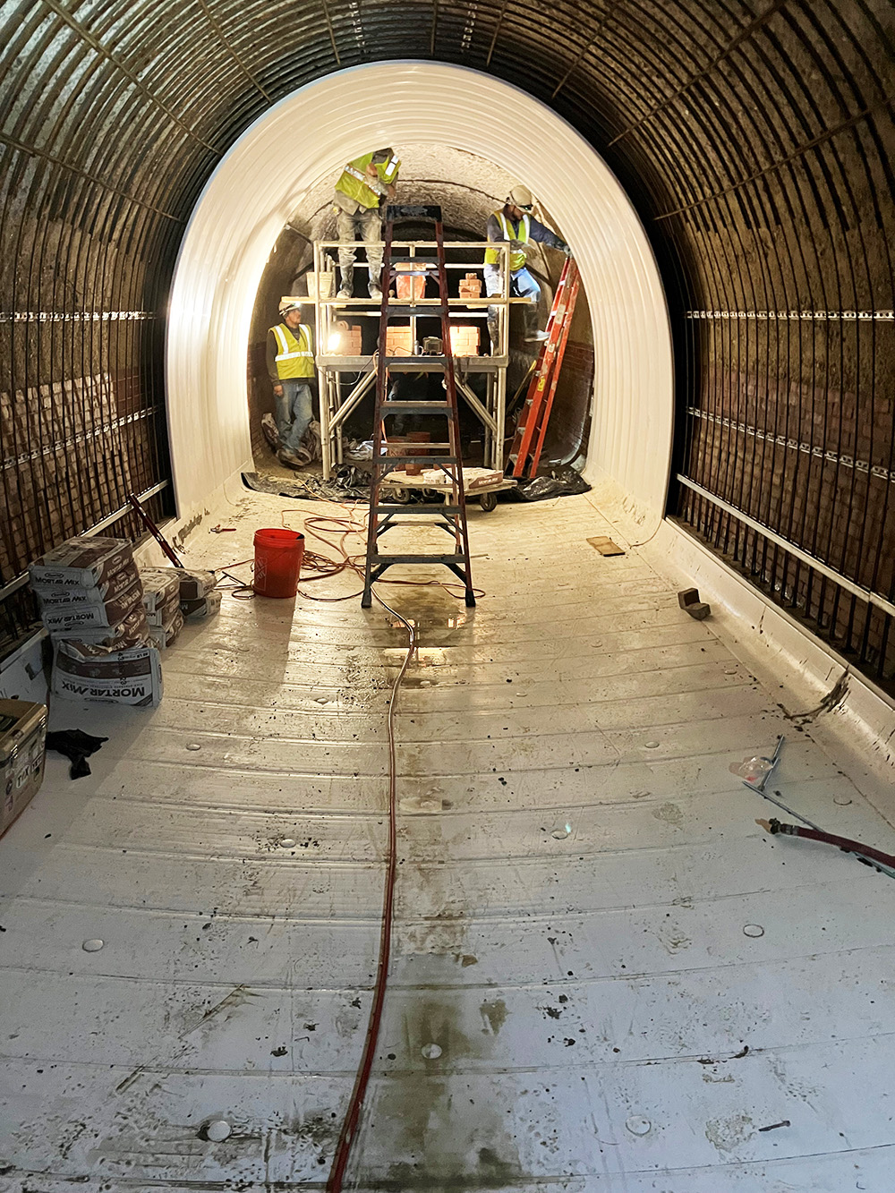
“Danby PL3E, 1-inch profile liner was installed using flat panels and curved corner panels. The floor panels were installed, then curved corner panels that would provide a transition from the floor to the top panels,” explained Cassel.
This process continued for the defined section. Once a floor section was completed, Boyer built a cementitious bulkhead, followed by the installation of the bottom (floor) buoyancy restraints that prepared the section to be ready for grouting.
The grouting process was completed in two phases, first was the floor and curved corner. After the floor was grouted-in, the side and top rebar was installed, then the 25-foot-long top panels were grouted in 14 controlled lifts.
The approved mix design was a blend of Type I-II Portland cement, Type “F” Fly Ash, admixtures and water that met the Danby requirement of 5,000 psi minimum compressive strength in 28 days.
“Grout had to be a minimum of 4 inches thick,” said Cassel. “Some areas required 15-plus inches, due to the extensive deterioration.”
Consequently, the composite cross-section of the rigid sewer pipe was much stronger than it had to be. “In the end, we achieved a Safety Factor several times its original strength,” said Grubbs.
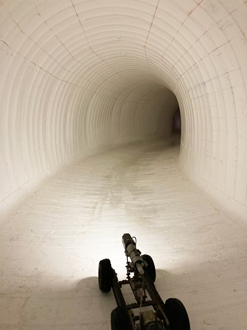
Danby lining system, alone, is a strong, structural solution, known for rehabilitating and protecting severely damaged pipe.
“At the same time, the system increases the pipe’s relative hydraulic capacity due to its greatly improved friction coefficient,” added Grubbs.
The City of Baltimore recognizes and appreciates the Danby difference – especially since several more miles of the BROI will eventually need to be rehabilitated.
Another fortunate result came through USC’s supporting role in the installation phase. The construction contractor received valuable hands-on training.
“USC is now qualified to install Danby, on its own, as a Certified Installer,” said Cassel. “Its crews have gone through the training we require for any company to install our Danby Lining System. We are proud to have USC as a Danby installer.”
FOR MORE INFORMATION
Boyer Inc., (713) 466-5395;
Danby PVC Lining (281) 598-1126;
Ulliman Schutte Construction LLC, (937) 910-9900

Comments