
March 2023 Vol. 78 No. 3
Directional Drilling
HDD and HDPE — The Perfect Match
Now Available: ASTM Guide for Use of Maxi-HDD Placing HDPE Pipe Under Obstacles
by Lawrence M. Slavin, Ph. D
ASTM F1962, Standard Guide for Use of Maxi-Horizontal Directional Drilling for Placement of Polyethylene Pipe or Conduit Under Obstacles, Including River Crossings, was originally approved in 1999, following development within the ASTM’s F17.67 Trenchless Technology Subcommittee. It was reissued in 2005 and 2011, and previously reinstated in 2020.
Corresponding changes to the document, if any, were minimal, including providing additional or updated references. The most significant was to the alternative guidelines TR-46 provided by the Plastics Pipe Institute (which has been superseded by its Municipal Advisory Board’s MAB-7), as more appropriate for mini-HDD operations.
However, the latest revision of ASTM F1962, approved in 2022, contains a significant change by providing the physical properties for the most-recent, high-density polyethylene (HDPE) material, PE4710. This material is significantly tougher than older, previous polyethylene (PE) products, facilitating successful completion of more complicated, difficult maxi-HDD projects.
Allowable pulling loads are based on a minimum tensile yield strength of 3,500 pounds per square inch (psi), with a significant reduction to limit non-recoverable viscoelastic deformation, as well as account for the effective cumulative load duration on the pipe (assumed to be 12 hours), resulting in a safe pull stress of 1,330 psi.
Its convenient methodology for selecting an appropriate pipe strength (wall-thickness), based on the project characteristics, has led to its increasing popularity and widespread usage within industry. ASTM F1962 is the only available ASTM standard for HDD.
Overview
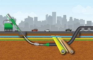
The ASTM document provides overall guidelines for a maxi-HDD operation, addressing preliminary site investigation; safety and environmental considerations, regulations and damage prevention; bore path layout and design; implementation; and inspection and site cleanup. FIGURE 1 illustrates the operation in a city or urban application.
One of the most significant contributions of ASTM F1962 is the provision of a rational, analytical method for selecting the pipe strength based on estimated installation loads on the PE pipe. Thus, ASTM F1962 provides a means of determining project feasibility, as well as initial design information.
Such results could be further refined by competent engineering expertise, including analysis of pipe and soil characteristics and interaction, often including the use of relatively sophisticated software tools, possibly based on the ASTM F1962 methodology. The procedure is straightforward and has been incorporated into various software tools, as an engineering and design aid for such projects.
The ASTM standard specifically addresses polyethylene (PE) pipe, a flexible product, for which the effects of any bending stiffness on drag forces at route bends or path curvature may be ignored. Relevant material properties for PE pipe, such as safe pulling tension/stress, are also provided in the document.
Because of its high ductility and flexibility, and ability to be fused in continuous lengths, per the well-established ASTM standards and by experienced contractors, PE, particularly high-density polyethylene (HDPE), is the most commonly used pipe product for HDD projects.
Although ASTM F1962 is intended for carefully designed, well-controlled maxi-HDD installations, the methodology has been extended, via appropriate assumptions and mathematical simplifications, to provide a simpler methodology that may be advantageously applied to typical, less-controlled mini-HDD projects.
This is the basis of MAB-7 (2020), MAB Guidelines for Use of Mini-Horizontal Directional Drilling for Placement of HDPE (PE4710) Pipe in Municipal Applications, as referenced in the 2022 edition of ASTM F1962.
FIGURE 2 illustrates a typical geometry for a maxi-HDD operation, in this case corresponding to a river crossing. The indicated bore/pipe path comprises three segments spanning the pipe entry (point A) to its exit point (point D), with horizontal projected distance Lbore, equal to the sum of the three horizontal (projected) segments L2, L3 and L4.
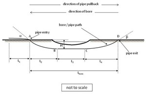
An additional length L1 exterior to the drilled path allows for handling at both ends and possible other effects (path curvature, thermal contraction, stretching, etc.). The intermediate horizontal segment, L3, may be of zero length. “Pipe entry” point is at the opposite end of the drill rig location, which coincides with the “pipe exit.”
Thus, FIGURE 2 shows the drilling operation proceeding from right to left, in contrast to FIGURE 1, where the drilling proceeds from left to right.
ASTM F1962 contains 10 main chapters or sections, as briefly described below, supplemented by several appendices.
Scope, referenced documents and terminology
ASTM F1962 addresses the overall planning and design, product selection and installation practices for the placement of PE pipe using maxi-HDD equipment. The primary focus is on commonly used high-density polyethylene (HDPE) pipe with a material designation code of PE4710.
For the larger diameters typically used for such applications, PE pipe is supplied in discrete segments that are fused together in the field, with essentially no loss in tensile strength, facilitating the pulling operation.
Preliminary site investigation (Section 4)
Both ends of the bore path must be investigated to confirm their feasibility for successfully completing the installation of the large, long pipeline. The drill rig and auxiliary equipment located on the pipe exit side are relatively large, and require water access, storage, and mixing and pumping facilities. The pipe entry side, opposite the drill rig, must accommodate the long length of assembled (fused) pipe.
In addition, there should be a detailed subsurface investigation, including test borings and soil analysis, to confirm the general suitability for the drilling operation, and to determine the appropriate equipment and hardware.
Safety and environmental considerations (Section 5)
Safety is a primary concern, during any activity, including construction utilizing maxi-HDD equipment and procedures. Potential safety issues fall into two general categories:
- Those directly related to the setup and operation of the maxi-HDD equipment (machine and hydraulic operations, as well as the drilling fluid under high pressure)
- Those associated with accidentally striking buried electric power lines or other existing pipelines.
Although not considered to be hazardous materials, the proper handling and disposal of drilling fluid is also discussed to avoid possible environmental issues.
Regulations and damage prevention (Section 6)
Depending on the location and extent of the operation, a variety of permits or approvals may be required, possibly from federal, state or local jurisdictions. These may include the need to file environmental, health and safety plans, or permits for passing beneath waterways, and there may be special requirements for drilling beneath railroads.
Bore path layout and design (Section 7)
The planned bore path, such as illustrated in FIGURE 2, must be consistent with the steering capability of the maxi-HDD equipment, and the bending capability of the drill rods. The stiffness of the steel drill rods determines their allowable curvature, in order to avoid fatigue.
Unnecessarily large curvatures (sharp bends) also contribute to bending stresses in the HDPE pipe, but generally are not significant for such a flexible product. Additional route bends, beyond those shown in FIGURE 2, as well as possible bends in the horizontal plane, should be avoided, and will increase the required pulling forces.
Pipe Design and Selection Considerations (Section 8)
Any pipe installed by HDD is subject to loads of a different type and/or magnitude than are experienced in other construction methods, including by direct burial in a trench. In addition to external pressures, due to the head of the relatively dense drilling fluid/slurry or subsequent (post-installation) soil loads, the pipe must withstand the axial tensions induced during the pullback process.
While the document provides useful information for evaluating the potential for collapse under lateral pressures, either during of following installation, the most widely used portion of ASTM F1962 are the formulae for estimating the pulling tensions corresponding to the leading end of the pipe reaching point A, B, C and D.
These formulae account for the frictional drag acting on the pipe along the surface of the borehole, primarily due to the high buoyant weight of the HDPE pipe, within the relatively dense drilling fluid, especially for vacant pipe. However, they are sufficiently general to consider the possible implementation of anti-buoyancy measures to reduce these otherwise high frictional forces.
The theoretical basis of the formulae for estimating the required pulling force is provided below.
Thus, a commonly used procedure for difficult or very long installations is to fill the pipe with water to reduce the buoyancy. In the absence of ballast, the maximum total calculated tension will typically occur towards the end of the installation; e.g., at point C or D.
The net resulting peak tensile stress is required to be less than the safe pull tensile stress of the HDPE pipe. Physical properties of the PE material(s) are provided in the appendices, which allow determination of an appropriate wall thickness for the pipe, depending on its diameter and estimated peak pulling force (or tendency to collapse). Software tools are based on the ASTM F1962 document and model.
Implementation (Section 9)
Due to the magnitude and complexity of maxi-HDD equipment and control systems, a well-trained, experienced crew is essential to plan and execute the operation. The initial decision involves selecting the size and capacity of the machine. At a minimum, it should be able to provide the necessary pulling force, based on the estimated required pulling force for the pipe itself, with possible additional capacity for accomplishing reaming.
It is important to properly use the drilling fluid for the initial pilot bore and reaming operations, and to accurately locate and track the bore path. The pipe must be securely gripped, including a swivel and possible breakaway link. As-built drawings must be provided, preferably supplemented with details of the soil characteristics and drilling operation.
Inspection and site cleanup (Section 10)
The HDPE pipe should not be cut prematurely. It should first be allowed to reach mechanical and thermal equilibrium, to avoid shrink back onto the bore hole. The exposed leading end of the pipe should be inspected for possible damage and a pressure or leakage test may be required, for fluid transport applications.
Appendices
Supporting the 10 main sections, several appendices provide the physical properties of selected PE material, as well as a means of determining the post-installation loads and pipe deflection. In particular, Table X1.1 provides the modulus of elasticity and safe pull tensile stress for HDPE (PE4710) and MDPE (PE2406) materials, as a function of load duration. Table X3.1 provides the critical collapse pressure for HDPE/PE4710 pipes as a function of load duration and wall thickness.
Theoretical basis for load estimation
The theoretical model used to develop the formulae for estimating the peak required tension (Section 8) assumes that the local frictional drag forces on the pipe are proportional to the local normal bearing forces applied at the pipe surface.
For flexible PE pipe, with minimal bending stiffness, the considered bearing forces are those due to the:
- Dead (empty) weight of the pipe above ground
- Buoyant weight of the submerged pipe, possibly reduced by use of ballast)
- Bearing forces resulting from (previously induced) tension tending to pull the pipe snugly against any curved surfaces (“capstan effect”).
In addition, the drilling fluid/slurry flowing along the length of the pipe also contributes, but is relatively low, based on the present model.
Frictional drag due to weight, buoyancy
In the absence of anti-buoyancy techniques, such as internal water ballast, the frictional drag developed within the borehole is generally much greater than that developed outside, because of the high buoyant weight for an empty PE pipe. For such cases, the buoyant weight of the submerged pipe, in combination with the corresponding frictional characteristics, is the major factor in determining the required pull force.
ASTM F 1962 provides formulae for determining the buoyant weight under various conditions. This weight is a function of the drilling fluid/slurry’s density, for which a conservatively high value is suggested for design purposes.
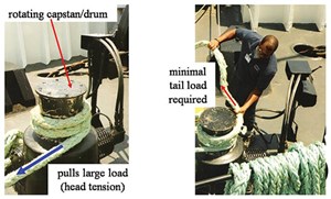
Capstan effect at bends
Although pipe stiffness effects may generally be ignored for flexible PE pipe, there is a potentially important effect can be due to route bends or any path curvature of significance. Tensions induced in the PE pipe, as it passes any curve, become amplified because the tensile forces tend to pull the pipe against the curved surface.
Such effects are independent of the pipe stiffness, pipe diameter, borehole clearance, radius of curvature or direction of curvature, and, in some cases become a major consideration due to their compounding effect. This phenomenon is referred to as the “capstan effect,” as it is the principle of the capstan winch, as illustrated in FIGURE 5.
For the geometry shown in FIGURE 2, with relatively shallow entry and exit angles, the associated load amplification due to this effect is not major; although for more complex paths, the effect could be very important. Mini-HDD applications, for instance, tend to contain bore paths with additional curvature because of the need to avoid known obstacles or follow a curved right-of-way, as well as more subtle curvature due to path corrections characteristic or typically less precisely controlled installations.
Hydrokinetic surface drag (fluidic drag)
The effect of shear forces directly imparted on the surface of the pipe by the drilling fluid (“fluidic drag”) has been handled in a widely disparate manner within the industry and is sometimes a major consideration. In contrast, the convenient model employed in ASTM F1962 results in a very low magnitude effect, which is directly added to the estimated pulling forces, due to frictional drag, including the capstan effect.
Summary
The recent (2022) edition of ASTM F1962 has revised the relevant physical characteristics of the PE materials, providing the physical properties for the most recent high density polyethylene (HDPE) material, PE4710. This material is significantly tougher than older, previously used PE products, facilitating successful completion of more complicated, difficult maxi-HDD projects. The physical properties of the PE4710 material allow greater pulling forces and also provide greater resistance to collapse. UI
ABOUT THE AUTHOR: Lawrence Slavin, Ph.D., provides outside plant consulting services as a member of IEEE, the world’s largest technical professional organization dedicated to advancing technology for the benefit of humanity. He can be reached at lslavin@ieee.org.

Comments