
July 2023 Vol. 78 No. 7
Features
Pressure pipe rehabilitation – what’s on the menu?
(UI) — Trenchless methods have been widely used for the rehabilitation of gravity pipelines for some time. The advent of these technologies and methods has lowered the cost of extending the useful life of gravity pipelines as opposed to outright replacing them.
In addition, the significant increase in value-added products in this market has created competition resulting in further technological development and cost reduction for extending the service life of critical assets. Due to the means of execution, trenchless rehabilitation methods are also inherently ecologically and socially friendly, especially when compared to traditional open cut pipe replacement.
For these reasons, trenchless technologies for rehabilitation continue to grow and evolve in the pressure pipe sector with immense benefits to the end-user. Shorter downtimes, less disruption to the environment, less economic impact to businesses and surrounding communities are readily observable effects of the development and improvement of trenchless technologies for pressurized water and wastewater pipelines. Perhaps most importantly, these variables have a considerable impact on the bottom line: cost.
Some trenchless methods for pressure pipes are well-known and have been widely used throughout the industry for decades with immense success. A brief overview of those technologies that migrated from gravity to pressure pipe applications is provided here, followed by a deeper investigation into a relatively new application known as flexible fabric-reinforced pipe (FFRP).
Cement lining, SIPP
A traditional method of protecting pipeline interiors is the factory application of a cement or mortar lining. In terms of trenchless rehabilitation, this method has evolved into spray-in-place lining or spray-in-place-polymer lining (SIPP).
SIPP is versatile in that it can be used to add a protective layer combating corrosion or physical deterioration, as well as restoring structural integrity to a pipeline. Depending on the desired structural performance required, this method can be applied in a thin layer (Class I), or in multiple layers (Class II and III), and can also be incorporated with a fiber mesh within layers (Class IV).
SIPP improves the hydraulic characteristics of the pipeline, eliminates the need to excavate tees or service lines, and is completed quickly relative to dig and replace. Challenges associated with this method include the need to shutdown and dewater the pipe for the duration of the application, extensive cleaning to allow for proper adherence of the material to the host pipe, removal of appurtenances throughout the rehabilitation span, and proper design of the applied material. Limitations also include an inability to repair more than minor corrosion holes and joint gaps and the fact that it requires diligent QA/QC throughout the application process.
Pressure pipe CIPP
Cured-in-place-pipe (CIPP) liner is an impregnated reinforced felt or woven polymer fiber hose with epoxy or vinyl ester thermosetting resin. This method is used extensively in gravity sewer applications and was one of the first trenchless technologies adopted on a large scale.
The resin-saturated liner is inverted into the host pipe with air or water and has traditionally been cured with hot water or steam but has now evolved into newer systems being cured with UV lighting. Properly executed UV-cured CIPP lining reduces wrinkles and other imperfections in the finished product, waste material and off-gassing of the curing resins.
Depending on the application, CIPP can be classified as a class III or class IV pipe. Today, CIPP lining has been successfully applied in pressure pipe rehabilitation applications.
Benefits of this method include fully structural rehabilitation capabilities, moderate internal diameter loss (compared to some other rehab methods), ability to span larger corrosion holes and joint gaps, ability to line long distances in a single day, elimination of pipe joints, and quick installation when compared to dig and replace (a theme likely recognized by this point with trenchless methodologies).
Challenges faced with pressure pipe CIPP lining include dewatering and cleaning the pipeline, removal of valves and other appurtenances throughout the rehabilitation span, laterals and other connections must be internally reconnected by robotic cutters or externally excavated and reconnected, resin/epoxy requires precise design and mixing, and the need for specialty equipment.
CIPP is also challenged by geometry, such as 22- and 45-degree bends that can cause the liner to wrinkle and/or “fold over” on itself, potentially creating an annulus that could compromise the integrity of the liner. CIPP is best fit for relatively straight pipe alignments. CIPP also requires constant, diligent QA/QC throughout the application process as ambient factors can influence the integrity of the liner.
Like the rest of the industry, CIPP manufacturers continue to make advances. The advent of UV-cured liner minimizes the potential for the catalyst setting off before the liner is in place, as it requires UV light rather than simple heat. Robotic cutters for re-instating services are constantly evolving, as well. Because of these and other advances, CIPP will continue to evolve and play a role in the rehabilitation of pressure pipelines.
Pipe bursting
Pipe bursting as a trenchless pipeline replacement method was developed and introduced domestically in the 1970s. The concept is relatively straightforward: a bursting or splitting head is pulled through the host pipe, breaking it by exceeding the pipe’s shear strength and tensile limits. Simultaneously, the bursting assembly expands the surrounding material to facilitate the pulling of a new pipe behind it.
Pipe bursting is a popular solution for replacing old, compromised or otherwise defective pipelines, as well as for upsizing a line due to capacity needs. Upsizing is generally limited to single “step” increases (e.g., bursting a 10-inch-diameter line and pulling in a new 12-inch pipe), although larger upsizing can be accomplished with the appropriate soil/surface conditions and host pipe depth.
There are two general methods of pipe bursting: pneumatic and static pulling. A pneumatic burst utilizes dynamic force to burst the existing pipeline, while static bursting is performed under constant pull force. Many factors must be considered when selecting the appropriate bursting method, including but not limited to, soil characteristics, groundwater presence, diameter and material of both new and existing pipelines, and depth.
Static bursting uses rods and a hydraulic system to pull the bursting head through the host pipe. It has become the most popular method largely due to the reduction of energy transition into the surrounding soil. The magnitude of energy waves associated with bursting can be extremely high and carry the risk of damaging nearby utilities or heaving at the surface (exacerbated if the pipeline travels below a roadway or structure). Upsizing the host pipe is exclusive to the static bursting method.
In general, high-density polyethylene (HDPE) pipe is the material of choice for pipe replacement via bursting. The flexibility and material characteristics of HDPE offer the ability to withstand pulling forces without deformation, the ability to string out long segments of pipe above ground (via weld fusion), and it has natural anti-corrosive properties.
Bursting offers key benefits when compared to other trenchless options, including no loss of pipeline internal diameter, the ability to upsize (if conditions are met), the ability to install long sections in a single day, and little-to-no host pipe preparation. Compared to traditional open-cut pipe replacement, installation time is reduced significantly, as well as necessary traffic control, restoration and permitting.
Pipe bursting is not without challenges and limitations, however. While gradual horizontal and vertical bends can be navigated successfully, bursting is limited to relatively straight alignments. Bends in the line must be identified and can limit the distances installed for a particular run. Appurtenances such as valves, tees, wyes, etc. must be removed before bursting and reestablished after.
Additionally, the risk exists for the bursting head to become stuck or go off-course at which point it must be located and excavated. A proper bursting effort requires extensive project planning to understand the existing pipe, soil and site conditions as well as the selection of the proper approach and materials.
Sliplining
Loose-fit pipe lining (commonly referred to as sliplining) is one of the oldest forms of lining, with roots dating back to the 1960s. Like pipe bursting, sliplining is performed by pulling or pushing a new pipe through a larger-diameter host pipe. Unlike pipe bursting, the host pipe remains intact and acts as a conduit for the new pipeline. As the name suggests, the new pipeline fits loosely inside the host pipe, leaving an annular space between the two.
This method of trenchless pipeline rehabilitation is perhaps one of the simplest and easiest to perform, and can be executed inexpensively. As with pipe bursting, HDPE is a popular choice for sliplining due to its advantageous material characteristics and structural capacity. However, other materials are frequently utilized, as well.
A clear limitation with sliplining as a rehabilitation method is the inherent reduction in internal diameter. Pressurized HDPE pipelines can require very thick pipe walls, therefore when sliplining high-pressure pipes with HDPE, the internal diameter is even further reduced and capacity can be impacted significantly enough to make the option unfeasible (although the smooth HDPE pipe typically carries a lower friction factor than the host pipe).
Preparation becomes critical in terms of understanding the alignment and cleaning the host pipeline to ensure that the new pipe can be properly installed. Any service or lateral lines must be excavated and reinstated after sliplining. The annular space between the new and host pipe is typically grout filled to close the void and provide support.
Modified sliplining or close-fit lining – what is colloquially known as Swagelining, is similar to sliplining in that a new standalone pipe is inserted into a host pipeline. Swagelining differs in that the pipe diameter is modified or reduced for insertion to the host pipe but restored to its original size and shape afterwards.
Once again, HDPE is the material of choice for this trenchless rehabilitation method because of its elastic properties. The desired length of HDPE pipe is fused together (up to about a mile in length) and then pulled through a dye stationed at the access point to the host pipe.
The dye temporarily compresses the HDPE as it is pulled into the host pipe; constant tension is applied to the pipe as it is being pulled to maintain the compressed shape. When the new pipe reaches the limit of the rehabilitation span, the tension is released, and the HDPE returns to its original shape and size.
The clear benefit of Swagelining as opposed to basic sliplining is that less of the original internal diameter is given up because the new pipe fits closely to the interior of the host pipe. The remaining benefits and challenges encountered with Swagelining are quite similar to sliplining, with additional equipment being needed to deform the new pipeline.
Flexible Fabric Reinforced Pipe
Flexible Fabric Reinforced Pipe (FFRP) has been successfully utilized in the United States for over 10 years but on the timeline of trenchless technology is still considered the newest rehabilitation option. There are currently two types of FFRP approved for use in the United States and both are considered AWWA Class III liners.
At a glance, the two available liners share many common traits both in material properties and installation method. Both options, in their standard form, consist of three layers:
- A modified, abrasion resistant polyethylene outer
- An inner fabric layer that provides the majority of the tensile strength
- A polyethylene inner layer that has a C-Factor of 150
Both products are best suited for pressure applications, as they cannot be tapped without compromising their integrity. Each FFRP option has a modified abrasion resistance polyethylene (PE) outer layer, a middle layer of fabric reinforcement (including options such as seamless woven polyester, aramid or a combination of the two fabrics), and a modified PE layer on the inside.
FFRP is an excellent solution for a wide variety of applications, especially those in which traditional open cut is challenged by above ground infrastructure, where CIPP is challenged by geometry, and where sliplining reduces the finished diameter too greatly. Other benefits include rapid installation times, long pull distances, small termination portals, small overall project footprint, NSF 61 approval for potable water, and installation regardless of ambient factors since no curing or bonding is required.
The manufacturing process, available diameters, and termination fittings are the primary differentiators between the two currently available products. One option is analogous to loose-fit sliplining in that it does not fit snug against the inside diameter of the host pipe. This product is manufactured utilizing a process that glues the three layers together. Assembly via glue limits the diameter to 20 inches, as the liner would come apart under its own weight during the installation process if larger diameters were produced. This product comes standard with a seamless aramid Kevlar fiber as the inner layer and two layers are available for higher pressure applications. The use of Kevlar does come with some restrictions as this FFRP system must be de-rated for pressure for each bend it navigates. In practice, however, this is typically not problematic as the original pressure ratings are sufficiently high enough to negate any de-rating.
The manufacturing process is the primary differentiator between the two products that are currently available: the alternative FFRP product consists of a reinforced fabric layer that is extruded within the inner and outer polymer layers, resulting in greater tensile strength and far exceeding the 20-inch diameter limitation. Both systems have a high coefficient of friction of 150 and are considered a class III pipe.
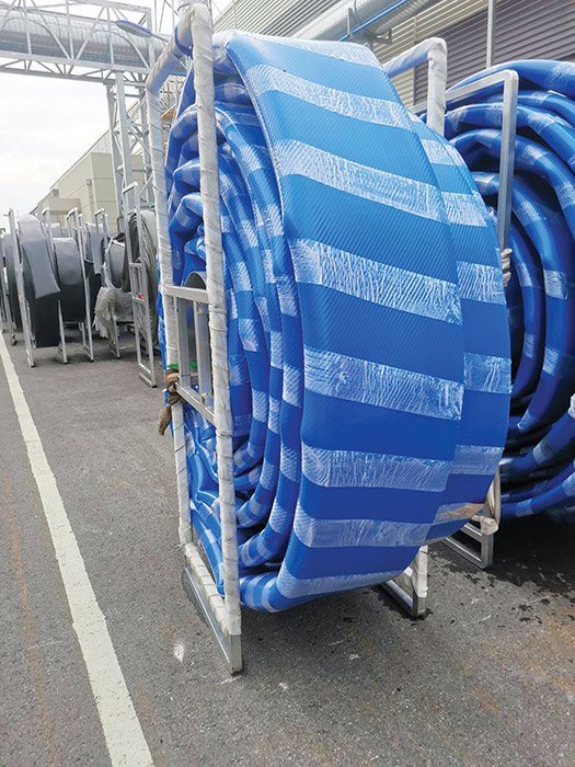
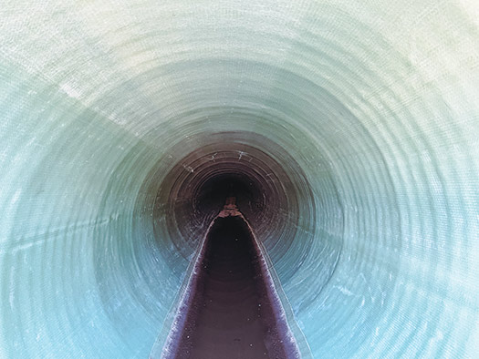
Pull lengths are generally dictated by appurtenances, pulling equipment capacity and the material characteristics of the selected liner. In small diameter applications, lengths of up to 8,200 linear feet can be achieved with glued FFRP liners, and up to 13,000 linear feet with the more monolithic liner. The difference in maximum pull capacity is again a result of the difference in layer bonding during the manufacturing process of the liners. Another consideration when planning pull distances is the spools that are used to transport and store the liners for installation. Larger pipe diameters can fit smaller lengths of pipe on the transporting spools to remain maneuverable. FFRP is fabricated round then flattened, folded, and taped for transportation to jobsite and for ease of insertion into host pipe. After insertion, air is introduced into the liner to restore it back to its fully round shape.
Benefits to this method include the following:
- Long segments can be pulled at once and result in zero joints
- Installation is quick when compared to dig and replace and to other trenchless methods
- Liners easily navigate 45-degree elbows wrinkle-free
- It be used on all types of pipe materials
- Installation is not depended on weather conditions
- No curing is needed
- Minimal diameter reduction (embedded liner even more so)
- Wide range of diameter options
- Requires minimal planning and calculations
- A small construction footprint is required
- A 40 to 50-plus year service life.
The drawbacks to this method include:
- Aggressive cleaning can be required
- CCTV is required to ensure that the host pipe is properly prepared
- All valves and services not only need to be removed and replaced but cannot be tapped directly back into the liner.
Conclusions
Trenchless technologies for pressure pipes continue to be favored over remove and replace methods. Overall, in most cases, a trenchless technology can reestablish the original life of the pipe, be more cost effective and be ecologically and socially responsible. Each of the above technologies has a unique purpose that fits certain situations better than the other technologies. Considerations that an asset owner must consider when selecting the appropriate trenchless approach include flow requirements, pressure needs, pipe classification, host pipe alignment and features, existing utilities and social/environmental impact.
Trenchless technology should always be considered as a method of reestablishing the useful life of a deteriorating pipeline. Each trenchless method brings with it certain advantages and disadvantages that must be considered when planning. However, with the improvements FFRP, it is the opinion of the author that a high percentage of future applications will favor this technology.
FOR MORE INFORMATION:
CPM Pipelines, (480) 438-1283, cpmpipelines.com
Comments