November 2018 No. 73 Vol. 11
Rehabilitation
Detailed Planning Helps Resolve Leak on Critical CWA 102-Inch Line

Greg Henry, P.E., LAN | Greg Olinger, P.E., CWA
A major component of the Texas Coastal Water Authority (CWA) is the Lynchburg Pump Station and three, large-diameter pipeline distribution systems that make up the Trinity River Water Distribution System. These three pipeline distribution systems, known as A, B and C Systems, deliver nearly 1 billion gallons per day of raw water from the Lynchburg Pump Station to the city of Houston’s East Water Purification Plant and industrial customers along the Houston Ship Channel, Houston’s Southeast
Water Purification Plant, Highway 225, and the Bayport area.
Shortly after rare major freezing weather in Houston on Jan. 19, the CWA identified a leak on the C-System at the end of Industrial Road adjacent to the Houston Ship Channel. The leak, which was on a 102-inch prestressed concrete cylinder pipe line, was flowing from the ground within CWA’s right-of-way near a private entrance road with almost non-stop heavy truck traffic.
Conveying approximately 250 MGD of raw water, the C-System is Houston’s primary water source feeding almost two-thirds of the city. Given its importance, CWA engaged Lockwood, Andrews & Newnam Inc. (LAN), a national planning, engineering and program management firm, to identify potential causes and repair methods, and perform a manned entry inspection of the water line. On Jan. 24, LAN met with CWA to begin various planning and coordination tasks.
Temporary fix
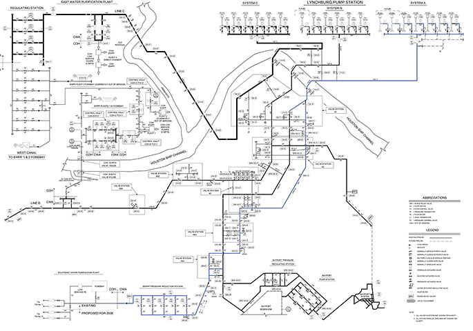
The raw water from the C-System is chlorinated at the Lynchburg Pump Station and conveyed to the East Water Purification Plant via a direct connection at plant 3 and a discharge outlet to the west canal, which feeds the forebay of plants 1 and 2 (Figure 1). Prior to decommissioning the water line, the project team considered several issues to minimize disruption to the Trinity River Water Distribution System and, most importantly, to the East Water Purification Plant and Houston’s water system.
“We knew that shutting down the C-System without adequate backup measures could result in low pressures throughout the Houston drinking water system and prompt a boil water notice,” said Melissa Mack, P.E., LAN’s principal and senior associate.

To avoid this problem, Houston needed a second raw water source that could temporarily feed at least 100 MGD of water to plant 3 at a minimum pressure of 15 – 20 psi during the shutdown. The project team evaluated several options and the challenges associated with each. The options included:
- Staging a series of pumps and HDPE pipe strings to transfer 100 MGD of water from Lake Houston’s west canal to forebay 3.
- Requesting some of the Houston customers to find alternate water sources during the shutdown.
- Channeling the raw water from CWA’s B-System to Houston’s 60-inch raw water line, which was out of service at the time, and then through Houston’s Low Lift Pump Station Direct Connection project, which was under construction.
The first option was expensive and necessitated several repairs to forebay 3 and its associated pumps that had been out-of-service for a long time. This option also required extensive changes to Houston’s chlorination treatment processes, as water would be taken from Lake Houston, a different source. The second option would inconvenience Houston’s customers and potentially disrupt their water supply. Given the limited time available and the critical nature of the C-System, the project team determined that these options were not feasible. Consequently, the project team decided to go with option three.
Low lift pump station direct connection
At the time of the C-System leak, the Low Lift Pump Station Direct Connection project at the East Water Purification Plant was nearing completion. The project consists of 36-, 42-, 48-, 54-, 60- and 84-inch sections of water line for transporting raw water from CWA’s B and C lines to the low lift pump stations at plants 1, 2 and 3 at the East Water Purification Plant. The project, which was completed in September 2018, allows the city to obtain raw water from a single source without having to pump into the forebay for plants 1 and 2, and provides redundancy to use either the B or C system at all three plants.
“At the time of the leak, more than 90 percent of the pipe had been constructed and only the control valves and electrical work needed to be installed,” said Mack. “CWA and the city decided to use temporary spools of pipe to fill the gaps and back-feed the water.”
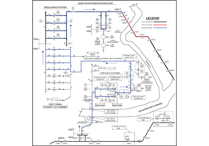
Subsequently, LAN performed hydraulic modeling to identify if the B-System water line, the Houston 60-inch raw water line and Low Lift Pump Station Direct Connection were capable of back-feeding up to 100 MGD of raw water to plant 3. The analysis utilized a newly built hydraulic model of CWA’s B-system in Bentley’s WaterGEMS, built in 2017 for its condition assessment program. Model updates were made for inclusion of system water mains, valves and system service line demands. Updated GIS files provided a geospatially correct model. Following the hydraulic modeling, the project team determined that this option could provide the 100 MGD of water the city needed (Figure 2).

Pipeline shutdown and repair
As the project team was working on the direct connection, CWA and LAN contacted pipe repair subcontractors to have contracts in place and materials and crews on stand-by in preparation for shutdown and manned entry.
During the planning phase, CWA procured 15 internal joint seals (WEKO-SEALS) from Miller Pipeline (the leak on the 102-inch line was assumed to be located at a joint within the pipeline). The 15 seals spanned the area of joints suspected to be leaking. Structural Technologies was put on notice to provide budgetary pricing for carbon fiber reinforced pipe rehabilitation and to complete as-needed and/or emergency repairs. CWA also lined up welders from the original pipe manufacturer (Gifford-Hill-American, now Thompson Pipe), if a welded repair was needed.
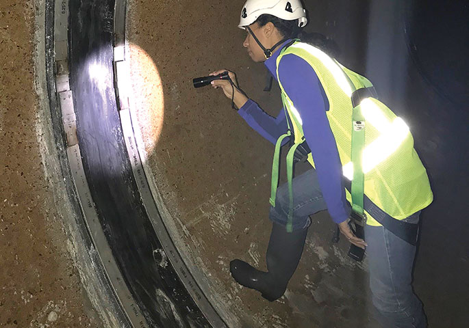
After detailed preparation, the C-System was isolated on Feb. 23 and dewatering was started by CWA crews later that night. Two days later, CWA staff and LAN engineers carried out a manned entry to identify the source of the leak and observe any other distress. Observations included identifying unusual circumferential and longitudinal cracks, disbonding of the concrete core, deficiencies in the manually applied joint grout, and other similar issues.
The results of the visual observations included:
- 177 pipe sections were visually inspected/observed (approximately 2,732 linear feet/0.52 miles).
- Installation of the pipe sections generally followed the manufacturer’s lay schedule.
- Interior joints overall reflected evidence of a good-quality, well-mixed grout application. Of the joints inspected, less than 5 percent had minor deficiencies.
- One welded joint (closure piece) was actively leaking, and one joint was suspected to be leaking.
- An abandoned air tap was found with evidence of severe corrosion.
- None of the pipes exhibited visible cracks, spalling or delamination of the inner concrete core.
One joint, more specifically a closure piece, was observed to be actively leaking. Because joint grout was intact, LAN was unable to identify the exact cause of the leak. The closure piece is welded on either side, which lead to the assumption of a cracked weld. Miller Pipeline immediately repaired it by means of internal WEKOSEALS. Three overlapping seals were needed to span the full width of the closure.
Another joint had a saturated grout and was suspected to have been another potential leak. Because joint grout was intact, the engineers were unable to identify if an active leak was present. Miller Pipeline installed a WEKOSEAL at this location for precautionary measures.
The remaining 12 seals were installed on the joints adjacent to the repaired active leak. The seals were positioned so they spanned the heavily trafficked private entrance road and covered remaining closure pieces. The installation was precautionary and performed because the C-System was shut down and dewatered.
The grout deficiencies identified during the manned entry were coordinated in-house by CWA, patched and repaired as a precautionary measure. CWA also coordinated in-house to perform a rubber plug and Quickcrete Mortar patching repair of the corroded air release valve outlet, which was previously abandoned from the pipe exterior but remained a potential, future leak point. The repairs were performed between Feb. 25 and Feb. 27, at which time the line was slowly re-pressurized and
returned to service.
Lessons learned, recommendations
Thanks to the exceptional planning between CWA, the city of Houston, LAN, Miller Pipeline, engineers and contractors involved in the Direct Connection project, as well as other contractors who were asked to be on standby for emergencies, the leak on the C-System was fixed in just five days.
The biggest lesson learned from this project is the importance of redundancy, said Mack. The Direct Connection project, once complete, will provide another critical water source. Houston is also looking at options to cleanup forebay 3 and rehabilitate associated pumps that have been out of service for nearly 20 years.
The project also showed the importance of relationships between CWA and the city, engineering consultants, contractors and manufacturers, said Mack.
“These kinds of emergencies can happen at the worst possible time and you have to be prepared for every scenario,” she observed. “We knew we could call Miller
Pipeline or Structural and they would be willing to hop on a plane the next day to address the issue.”
To prepare for future events occurring along the water line – including transient events, major construction activities or changes in system operation – LAN engineers provided a set of recommendations.
Periodic Monitoring: The observed condition of the water line during the manned entry was for a snapshot in time. To maintain up-to-date knowledge and correct problems before they resulted in a failure, engineers suggested monitoring the water line periodically to track the progression of deterioration. This can be accomplished through acoustic monitoring or electromagnetic inspections. Understanding the rate of deterioration provides a higher level of confidence in the pipe’s performance in the event conditions in and around the water line change (e.g., increased pressure and flow due to planned shutdowns of other lines in the CWA’s water system) and help identify the need and timeline for any additional rehabilitation.
Maintenance and operations: This line was originally designed to a working pressure of 100-130 psi at the repaired leak location. CWA currently operates the transmission pipeline at pressures well below this limit. LAN recommended that maintenance staff be trained and alerted to the risks involved if pressures are increased beyond a certain limit without fully assessing the waterlines condition. Coupling a warning system to the in-place pressure gauge is a measure that can be taken to assist maintenance staff. For example, an email warning could be established to notify employees when the pressure exceeds a set number.
Action Plans: To extend the remaining useful life and provide a more reliable level of service for the water line, short-term and long-term action plans were also recommended.
Short-term action should be implemented, based on priority, within a two- to five-year period, such as rehabilitation of valves and cathodic protection investigation.
Long-term action should be completed within a five- to 10-year or longer period. These include conducting periodic inspections and tests to confirm operability of isolation valves and surge protection devices. Although manned entry of the water lines requires extensive planning and is a large expense to CWA in money and manpower, it provides the best possible assessment of actual condition. Manned-entry visual inspections and electro-magnetic testing survey should be done at least every 10 years.


Comments