
March 2017 Vol. 72 No. 3
Features
Shore Approaches For Fiber Optics Cable In Arctic Conditions
By Brian “Butch” Webb and Zachary Casey
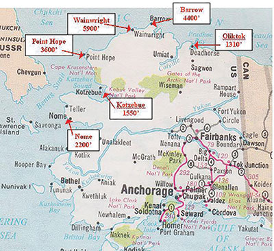
A communications company is installing a subsea fiber optics cable from Europe to Asia around North America through the Beaufort and Bering Seas. At various points along the main line, branching units are installed to allow for branch legs to be laid to various villages along the coastline of Alaska. These branch legs will provide vital telecommunication service to remote communities and businesses. The villages include Nome, Kotzebue, Point Hope, Wainwright, Barrow and Oliktok Point (Prudhoe Bay). (Map shows locations and HDD lengths.)
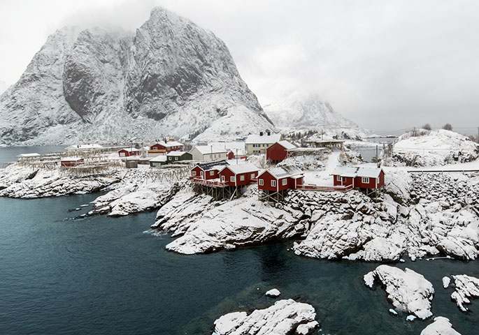
The coastline of Alaska is typically very remote, populated by few towns and accommodations, with the exception of Prudhoe Bay, where industry consists mostly of fishing and some tourism. The weather is Arctic conditions and the ocean freezes over almost nine months of the year, preventing boat traffic. Ports are non-existent and material, equipment and manpower is usually lightered from ship to shore. As a result, projects preformed in the Arctic require very careful planning and scheduling.
For the purpose of this project, historical geology of the Arctic began 26,000 years ago, when the ocean level was approximately 400 feet lower than it is today. This was caused by the Ice Age. As a result, the exposed ground froze. As sea levels rose to current levels, the permafrost remains frozen beneath the sea bottom. Minimal geotechnical sampling has indicated that permafrost temperatures in the soil as shallow as 100 feet below sea bottom can be as cold as 15-17 degrees F.
Other problems encountered as a result of Arctic conditions include logistics to bring labor and equipment to the jobsite. The Arctic is sparsely inhabited and roads are non-existent. The only method of shipping is by air or water when the ocean ice has moved offshore. Therefore, scheduling is important, and lightering operations must be carefully planned to ensure the transportation of heavy drilling equipment can be safely transported from cargo barges to shallow beaches. This generally involves the use of landing craft specifically designed to serve Arctic Alaska.
Lodging and crew accommodations are a problem because few hotels exist in the small villages, and housing and meals have to be provided. Walmart stores do not exist in this region; therefore everything needed has to be brought in when mobilized.
The Arctic environment is fragile. Tundra, when disturbed, may scar and take years to heal. Shorelines are used by the Native Americans for fishing, and major disruptions can cause economic hardships.
Project specifics
To bring the subsea cable branches to shore from the main cable, various techniques were considered for the shore approach, including traditional beach trenching, as well as horizontal directional drilling (HDD).
The technique of trenching the shore approach would include traditional methods of excavation to Mean Low Level Water and jet plowing from the water’s edge, to a depth beyond, to the cable. This technique is used in the Gulf of Mexico and also worldwide. However, the known risk from deep ice scour in shallow water would require burial depths that are unachievable with standard methods. Additionally, the large volume of material removed and the consequent stockpiling of the spoil presents an environmental problem in the Arctic that is not acceptable. The HDD technique eliminates this problem and can extend the shore approach further out to sea without the need for any sea bottom plowing or excavation of fragile arctic coastline.
The HDD technique for telecommunications and power cables normally includes the horizontal bore of a pilot hole from shore, the reaming of the pilot hole to larger dimension and the back pull of a HDPE casing through the reamed bore to be used as a cable conduit. This technique was not acceptable because of logistics and cost. The HDPE casing would have to be fabricated on the Tundra, and pulled offshore and then pulled through the HDD bore, which is a high risk. Additionally, the durations required for the
pull back of HDPE casing exposed the drill to freezing seawater entering the bore. As a result, the drill string used by HDD for the pilot hole was selected to be used as the casing.
Care was taken to select double white band S-135 drill string with a large diameter to accommodate the armored fiber optic cable to be installed. Tool joints with gradual tapers were selected to minimize the risk of cable damage from friction during pull in of cable.
Extensive oceanographic surveys conducted since 1978 indicate that the severe risk from ice scour of buried cable had to be addressed. The work led by M. Mellor for the Cold Regions Research & Engineering Lab definitively proved the risks of ice scours to cables and pipelines in the Beaufort & Chuckchi Seas. Ice scour trenches were measured at a depth of 10 feet to a water depth of approximately 150 feet. To prevent communication disruption, the fiber optics cable had to be buried to a cover depth of 10 feet. See Exhibit 2 for ice scour phenomenon.

Exhibit 2 – Arctic Subsea Ice displacement
Solutions
Because of the severe Arctic conditions and short work span, the project required a well-planned and comprehensive work schedule. Every detail of the work, labor, equipment and material had to be accounted for. The location and duration for housing and accommodations had to be established well in advance. Government permitting was essential.
Scheduling included studies of the timing for ocean ice melts and freeze-ups. Frequency and duration of storms and excessive ocean currents had to be addressed, as did mobilization and shipping times. Any delays that put the project into ocean freeze-up would delay the completion for one year.
The HDD bores were unique because the drill pipe was used as the casing. The HDD bore lengths range from 1,550 feet to 5,900 feet. Following mobilization to the jobsite, landing craft were used to deliver the HDD equipment to shore. The equipment barge was used as a diving platform at the HDD subsea end. (See Exhibits 3, 4 and 5 showing the dive barge.)
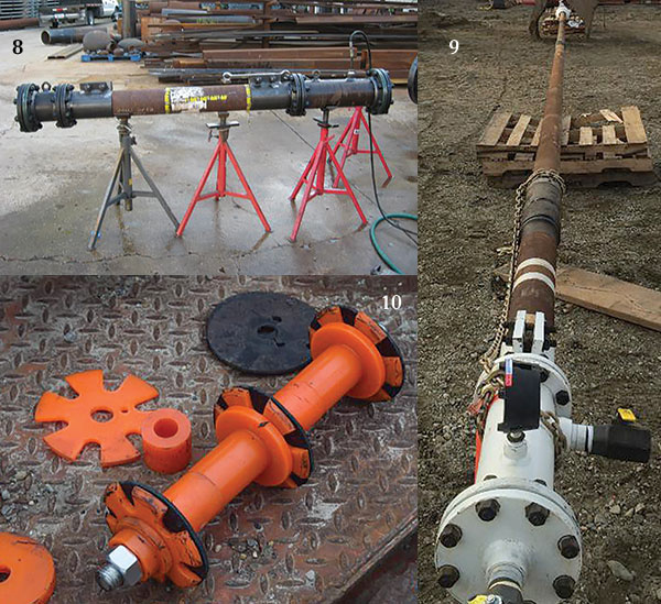
The HDD equipment was set up and the bores completed. (See Exhibit 6 for HDD bore equipment.) The HDD bores penetrated the ocean bottom at a water depth of 50 feet, thus the bore lengths varied with each location. (See Exhibit 7 for a typical HDD bore.) During the bore, the friction of the drill string and heat from the drilling mud prevented freezing should the drill string have traveled through permafrost. To prevent freezing of the liquid inside the drill string, a system was devised to replace the liquid with air. This included a pigging system with pig traps, special pigs and an air compressor. (See Exhibit 8 for pig traps under test.)
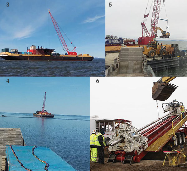
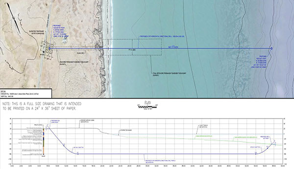
Exhibit 7– RTC Landfall Bore Profile
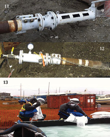
The drill string consisted of drill pipe with upset connections both inside and outside, thus producing internal dual diameters. The diameters were approximately 5 inches for drill pipe and 4 inches at the joint. Therefore, a dual diameter disc pig was custom designed and fabricated. (See Exhibit 9 for the dewatering disc pig, and Exhibit 10 for test pipe used to test dewater disc pig.) The drill string was not sized for standard line pipe; therefore, off-the-shelf pigs were not available. This also presented a problem for the pig traps. Standard pipe fittings had to be machined and modified to fit on the ends of the drill string pipe. The pig traps were fabricated and were tested by installing on a section of drill pipe (see Exhibit 8). In addition to a pig receiver on the subsea end, a subsea valve was installed to prevent water from entering the drill string after pigging. (See Exhibit 11 for pig receiver and basket.)
The procedure for dewatering the drill string began with the divers cutting off the drill bit from the drill stem and removing the drill bit. Following this, the divers installed the subsea valve on the drill string and the pig receiver to the subsea valve. A hose was connected to the receiver and ran from the subsea receiver to the barge deck. The hose was chosen over the receiver basket because divers were not required to witness the pig enter the basket and then close the subsea valve to prevent seawater entering the drill string. On some HDD approaches, several hours of dive time were lost due to tidal currents.
Onshore, the drill string was cut and the pig launcher installed. (See Exhibit 12.) A disc pig was loaded into the launcher and run using an air compressor. When the pig arrived on the barge deck, the subsea valve was closed.
The installation of the fiber optics cable was to take place a year later. Therefore, the drill strings were to be charged with air to 70 PSI to prevent seawater from entering. However, the pressure couldn’t be maintained and the reason couldn’t be determined, with speculation ranging from a leak at the receiver and the subsea valve, or one of the many pipe string tool joints. To solve this problem, the drill string was filled with a salt brine that had a freezing point lower than the permafrost. (See Exhibit 13 for brine tank.) A procedure was followed that diluted the salt brine when the salt brine was removed from inside the drill string.
Fiber installation
Installation of the fiber optics cable will begin soon by pumping water into the drill string from the shore to the subsea valve to ensure the drill string has not frozen. Following the water, a soft foam pig could possibly be run to indicate a full opening hole is available to allow passage of the pull pig. If the soft foam pig run is successful, a wire line will be attached to the pull pig and pulled to the subsea valve. A cable seal was developed to prevent excessive leakage while the pig was being pumped through the drill string
Divers will attach a fiber optics pull rope to the wire line and the rope pulled to the pig launcher end and attached to a fiber optics pull winch. The pull rope will pull the fiber optics cable through the drill string to shore. During the design, testing and operations, extra precautions were taken to prevent any sharp edges from coming into contact with the fiber optics cable during the pull operation. This included the tool joint ends and the cutoff section underwater and on land. Clean up operations will complete the land portion of the project.
Special equipment unique to this project included the pig traps and pigs. To ensure the pig traps fit the drill pipe, special fabricated fittings were developed to seal against the pipe and not leak. In addition, the traps had to be attached to prevent slipping off the ends and possibly causing injury.
The purge pig was a typical multiple-diameter disc pig to negotiate the internal upsets at the tool joints. However, when tested as a pull pig, the disc pig was not acceptable. Therefore, a test site was set up and a pig was developed that would pull 1,400 pounds at 160 PSI without leakage, even though design estimated a maximum pull of 1,000 pounds. The pressure drop required to push this pig through the tool joints was thought to be excessive, so the center cup was removed. However, if additional pull is required, the center cup can be installed.
This type of operation under Arctic conditions required very careful planning. The window of operations is short because of the ice conditions, which can be as short as two months. Due to the cost of mobilizing HDD, dive and construction equipment, including barges, landing craft and manpower, cannot be shut down because of one piece of the operation; therefore, everything was thoroughly tested prior to shipping to the jobsite. Any failure causing a delay may postpone the project for another year. Planning is paramount.
About the authors: Brian “Butch” Webb, BKW Inc., Tulsa, OK; and Zachary Casey, R.T. Casey, Bel Chasse, LA.

Comments