
January 2015, Vol. 70, No. 1
Features
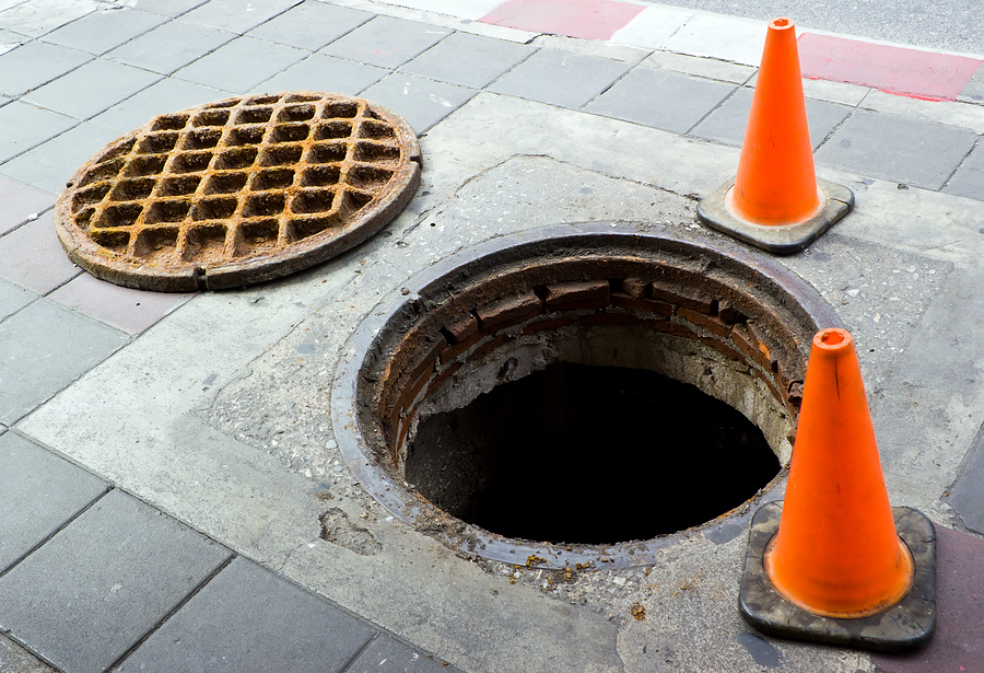
Exploring Wall Thickness Requirements For Manhole Coatings, Liners
The discussion around the proper design methodology of coatings and liners installed in sanitary sewer manhole structures is creating quite a roar in some circles these days.
Consulting engineers wanting to do the right thing by their owners have been left to themselves in seeking out the answers as to how to design the various rehabilitation systems because the providers have been unable to reach a consensus within the ASTM F36 subcommittee tasked with this challenge. Whether this lack of reaching a consensus is based upon poorly thought-out design methodologies or politically motivated attempts to thwart one manufacturer’s design beliefs over another manufacturer’s design beliefs is not known to this author. Nevertheless, the industry still needs a design methodology.
That being said, at least one and possibly two manufacturers have suggested that the wall thickness design should be made using the equation X1.1 of the ASTM F1216 design appendix A which was written for the partially deteriorated design condition for flexible liners installed in buried pipes. However, the liners being installed in buried pipes are, by definition, horizontally-oriented, cylindrically-shaped, un-bonded thin shells; not vertically-oriented, cylindrically-shaped thin shells. The basis for this recommendation appears to have begun with an unpublished paper written sometime between 1995 and 2000. A careful review of this paper, however, has revealed several flaws in the paper’s authors’ analysis.
The first flaw is that the engineering basis of the equation X1.1 is that the load along the axis of the cylindrical shell is essentially uniform when it is not. For a vertically-oriented, cylindrically-shaped shaft, the load coming onto the coating or liner is linearly increasing with the depth of bury.
Secondly, the authors assumed that the modification factors added to the equation X1.1 for pipe liners to account for the tight encasement of the shell and the impact of any ovality in the cylindrical shell created by the host structure that were empirically derived for the horizontal orientation, would also be valid for the vertical orientation as well. No such work has been done to date to validate these modification factors’ applicability in the vertical orientation of a manhole with a linearly increasing load acting on the shell. Thus, the paper as written assumes incorrectly that the technical basis upon which Timoshenko’s equation for the uniformly loaded un-encased cylindrical shell can be rationally applied to that of the linearly increasingly loaded shell. Confronted with these facts, one must ask how then if coatings and liners used in manhole rehabilitation be designed.
Initiating design process
Analogous to the design of coatings and liners for buried pipes, the design engineer must initiate a design process for these systems with a collection of the information on the current condition of the subject soil structure interaction system. Properly estimating the state of the stresses in this system is essential to designing a rehabilitation system that has a reasonably strong chance of surviving the desired service life in the renewed condition (i.e. 50 years). The second step in the design process is to define the needed in-place performance parameters that will govern the selection of the technically applicable alternative(s) that have the capability of meeting these performance criteria.
The current condition assessment of this soil structure interaction system needs to look at the following items:
• Materials of the subject manhole’s construction;
• Level of any wall loss;
• For brick manholes… missing mortar and/or bricks; and
• For concrete manholes, loss of wall thickness;
• Corrosive conditions present in the manhole’s environment;
• Level of any corrosive gases;
• pH of the manhole’s wall surfaces; and
• Evidence of microbiological corrosion organisms;
• Condition of the soil surrounding the structure;
• Signs of infiltration through the wall of the manhole
• Characterization of the water flow (weeper, runner, gusher, etc.); and
• Elevation of the water table (phreatic surface)
• Surface conditions;
• Surface improvements (unpaved, roadway, etc.);
• Type of live load at the surface; and
• Evidence of freeze-thaw action distress.
Examples of the typical in place performance parameters are:
• Corrosion barrier – the coating or liner is required to isolate the existing manhole from the corrosive elements in the atmosphere or in the fluid flowing in the pipes the manhole supports in order to minimize or arrest any further deterioration of the manhole wall structure;
• Infiltration/Inflow barrier – the coating or liner is required to arrest further groundwater intrusion either by gravity flow of through the soil into openings or voids in the wall structure or by pressure due to the location (elevation) of the phreatic surface;
• Restoration of the wall surface – this is typically a cosmetic improvement; it is often referred to as re-profiling of the wall surface; and
• Structural enhancement – the coating or liner is required to mend the wall structure which is visually found to be “moving.” Typically, this is done for brick manholes where a substantial amount of the masonry is missing and it is desired to “fix” the bricks in their current position to assure a long-term renewal is accomplished.
The above in place performance parameters are assessed by whether the applicable technologies are acting either as a bonded cylindrical thin shell or an un-bonded cylindrical thin shell. The bonded systems analysis is pretty straightforward as they are not typically sensitive to variations in the radii of the existing manhole structure and therefore their thickness is a function of the thickness required to ensure their performance in the site specific requirements of corrosion protection, water intrusion barrier and structural enhancement.
Handling live loads
Centrifugally cast-in-place mortars such as AP/M’s Permacast PL-8,000 have been found to be sufficient structurally to handle the horizontal live loading and hydrostatic loading at depths up to 185 feet with only a 1.0 inch finished thickness (measured above the peaks in the wall surface’s profile). This is very well documented in John Pitt’s 1994 report on his research work that was funded by the National Science Foundation.
Epoxy coatings have been formulated to achieve very good levels of adhesion to the existing manhole wall surface (500 to 1000 psi) even when applied to a damp substrate. While a water-tight, chemical resistant barrier can be achieved with as little as 60 – 80 mils (0.060 – 0.080 inches), the actual minimum or nominal wall thickness required is actually dictated by the service environment and the surface profile of the structure being renewed. Below is a listing of the general guidelines given by the industry for various materials to which the coating or liner is being applied:
• Concrete, new/smooth: 80 – 100 mils for immersion, 60 – 80 mils for atmospheric, splash and spill exposure;
• Concrete, rough: 100 – 125+ mils;
• Masonry/Brick: 125 – 150+ mils;
• Steel: 25 – 80 mils for immersion, 18 – 60 mils for atmospheric, splash and spill exposure; also profile dependent.
Using proper quality assurance testing to verify the required wall thickness has been applied and the level of adhesion with the wall surface of the structure is present, the typical manhole structure would only need to resist the external hydrostatic load in any isolated areas where the adhesion was assumed to be not present as the result of a failure to find it during the QA testing or possibly to be lost over time. For example, a 4.0 inch un-bonded area of an epoxy liner that is 125 mils (0.125 inches) thick subjected to an external hydrostatic pressure of 15 feet continuously for 50 years potentially could be lifted (a “blister” formed) approximately 0.02 inches at the center which equates to a tensile strain of 0.02 percent; well below the material’s strain capacity of 1.5 percent. Therefore, isolated un-bonded areas of the epoxy liner would be quite capable of handling this possibility.
Materials that by their nature will act as an un-bonded, cylindrical thin shell would need to have their required wall thickness determined based upon the level of deformation produced in the shell by any external hydrostatic pressure which could, in turn, lead to a loss of water-tightness at the bottom of the vertical wall area if not restrained against movement by the design of the bottom’s renewal. Manhole renewal systems that typically fit into this category of lining are the cured-in-place liner systems adapted from the pipe lining industry (both the un-reinforced and reinforced systems), spray-on polyurethane liners, and other polymeric lining materials that cannot reliably achieve adhesion. This is due to their rapid curing or other installation factors that can come into play in the damp environmental conditions that are routinely found in a sanitary sewer manhole.
Proposed testing
Currently a finished analytical solution doesn’t exist for this category of manhole liners. An experimental testing program has been proposed to CUIRE to be integrated with their research project for WERF on manhole liners that is already underway that will hopefully produce the necessary data to allow the WERF project team to develop an analytical model for the un-bonded cylindrical thin shell systems. The seventh edition of Roark’s Formulas for Stress and Strain (table 13.2, case 6) has the analytical solution for the un-encased solution for these systems; but it must be refined to fit the encased condition and to match the real world variable of any out of roundness in the cylindrical shell (as was done for the case 5 which was the basis for the earlier referenced equation X1.1 of F1216).
Engineers can today confidently require the finished thickness of cementitious and epoxy liners (bonded) in manholes up to 30-feet in depth without the need for a site specific wall thickness design analysis. The 1.0 inch thickness recommended in Pitt’s study is very capable of the external hydrostatic load even with the phreatic surface at the top of the ground. The engineer, however, does need to do their homework to determine which mix design will provide the proper corrosion resistance for the environment inside the manholes being renewed. Epoxy liners applied in a thickness between 125 to 150 mils should also be capable of resisting any external hydrostatic pressure to this depth and to provide for the barrier required to provide good corrosion resistance and structural enhancement. Proper attention to performing the specified quality assurance testing is key to confirming that this design recommendation is achieved in the field by the installer.
In the interim, as we await the results of the WERF study being performed at CUIRE, we must rely on a Finite Element Analysis solution or the un-bonded shell material’s engineering department to guide us with any in-house empirical solutions they may have on their particular material to arrive at the required wall thickness for the site specific conditions of the manholes to be renewed.
ABOUT THE AUTHOR:
Norman “Ed” Kampbell is a civil engineer and president of Rehabilitation Resource Solutions. He has extensive background in the engineering, design and research of sewer and water piping infrastructure. Kampbell is considered one of the industry’s leading authorities on rehabilitation methodologies including effectiveness and performance.

Comments