
September 2021 Vol. 76 No. 9
Features
Mini-HDD for Placement of HDPE Pipe in Municipal Applications
By Dr. Lawrence M. Slavin
A new set of guidelines for the use of mini-horizontal directional drilling (mini-HDD) has been developed by the Municipal Advisory Board (MAB) of the Plastics Pipe Institute (http://plasticpipe.org).
Previously available as Technical Report TR-46, the new document, MAB Guidelines for Use of Mini-Horizontal Directional Drilling for Placement of HDPE (PE4710) Pipe in Municipal Applications, specifically addresses water lines, including potable water and sewer. Designated as MAB-7, the document provides detailed information for both IPS- and DIPS-size pipes, constructed of the latest PE4710 material.
The document is analogous to ASTM F1962, Standard Guide for Use of Maxi-Horizontal Directional Drilling for Placement of Polyethylene Pipe or Conduit Under Obstacles, Including River Crossings, but at a level appropriate for the less complex mini-HDD technology, and typical project characteristics, as compared to maxi-HDD installations.
Technical Report MAB-7 comprises 10 main sections, plus six appendices and references. In particular, guidelines are provided for proper drill rig positioning, consistent with meeting required placement depths and drill rod capabilities. In addition, it provides a practical methodology for estimating the relevant forces and effects present during installation, based on the route geometry, facilitating proper selection of the pipe wall thickness.
Bore planning, rig setup
FIGURE 1 illustrates a typical mini-HDD bore vertical profile trajectory, including occasional pits along the route. These pits may be required for pipe splicing, completing lateral connections, or to expose existing utilities. FIGURE 1 designates certain points along the bore path and their relative distances from the drill rod entry or exit points.
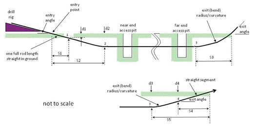
These distances are a function of the entry angle and drill rod characteristics (e.g., allowable radius of curvature, or “bend radius”), and determine the setup location and space requirements in which to perform and complete the pipe installation. For pipe constructed from HDPE, the bend radius limitation of the drill rods is sufficiently large to be compatible with that of the product pipe.
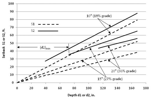
FIGURE 2 shows the required setback distance of the drill rig corresponding to the distances shown in Figure 1 and also indicates the minimum possible depth for a level trajectory.
Pipe design, selection considerations
The guidelines indicate that essentially all the commonly used wall thicknesses (e.g., DR 7 to DR 17) for HDPE (PE4710) pipe would be sufficiently strong to resist collapse for depths to approximately 15 feet, with the possible exception of DR 17, the typical limit for mini-HDD installations. A limit of 10 feet may be more appropriate for DR 17.
These depths assume an empty pipe during the installation and pre-operational phase, in the absence of internal fluids or pressure, which would offset the effects of the external pressure due to drilling fluid/slurry. For depths greater than 15 feet, thinner wall pipe, or special situations, the adequacy of the product for the application should be verified using the information provided in the appropriate appendix.
The following equation was developed as a convenient means of estimating the peak force applied to the pipe as it is pulled throughout the bore hole:
Tension (lbs) = [Bore Length (ft) × Buoyant Weight (lbs/ft) × (1/3)] × (1.6)n
The buoyant weight may be calculated as:
Buoyant Weight (lbs/ft) = ½ [Pipe Outer Diameter (in.)]2 – Pipe Weight (lbs/ft)
The parameter n is equal to the number (or fraction) of 90° route bends due to cumulative route curvature, where n = n1 + n2. The quantity n1 is the effective number of deliberate/planned 90° route bends, and n2 is the cumulative curvature (90° route bends) due to the unplanned undulations. The following value of n2 is suggested:
n2 = [Bore Length (ft) / 500 ft] × [2-in / Rod Diameter (in.)]
Criteria for selecting an appropriate pipe strength then corresponds to selecting a DR value with a safe pull tension at least as large as the estimated tension, as determined above.
The safe pull tension for the PE4710 pipe is given below, for both IPS and DIPS sizes. The quantitative values shown are based on the minimal required wall thickness, as opposed to that of the actual manufactured product and, therefore, underestimate the average safe pull tension by approximately 6 percent.

The results illustrated in FIGURE 3 confirm placement distances of more than 800 feet, even for the DR 17 pipe, beyond the limit for typical mini-HDD operations.
It is noted that the mini-HDD calculations generally result in considerably shorter possible placement distances than that corresponding to application of the methodology and equations provided in ASTM F1962, which may also include the use of anti-buoyancy techniques to reduce buoyant weight and significantly reduce required pull loads.
The shorter placement distances for mini-HDD are also due to the increased drag (“capstan effect”) generated by the additional route curvature of mini-HDD operations, due to path corrections. These corrections are typically of greater magnitude and significance than that encountered in well-controlled maxi-HDD installations.
In general, other methods for determining pulling loads, including available software tools, are typically based on well-controlled maxi-HDD installations and not representative of actual mini-HDD applications with respect to anticipated pull loads.
Although the MAB-7 guidelines are primarily described with respect to mini-HDD operations, the information may also be applicable to midi-HDD installations. Thus, midi-HDD guidelines and associated practices may be obtained from the MAB-7 document and/or ASTM F1962, depending upon the particular application and the judgment of the contractor or engineer.

Comments