
November 2018 No. 73 Vol. 11
Rehabilitation
Pressure Pipeline Rehabilitation Testing Requirements Bridge Technological Gap

EDITOR’S NOTE: This is the third in a three-part series on pressure pipe presented by the NASSCO Pressure Pipe Committee. There will be an in-depth program track on these topics and more at UCT, Jan. 29-20, 2019, in Fort Worth, Texas. For more information, visit the UCT website at uctonline.com.
Pressure pipeline rehabilitation technologies are designed to accommodate a wide range of host pipe materials, conditions and applications such as potable water, raw water, sewer force main or industrial settings. Lining systems can be included as one of the following processes:
- Cement mortar lining (CML)
- Spray-on polymer lining (PL)
- Cured-in-place pipe lining (CIPP)
- Close-fit lining (CFL)
- Sliplining (SL)
Structural classifications of linings are loosely defined within the AWWA Manual of Water Supply Practices M28, Third Edition, Rehabilitation of Water Mains, which does not offer design guidance. American Water Works Association (AWWA) and ISO committees have been working toward bridging the technological gap to provide clarity to these classifications by introducing definitions and testing requirements.
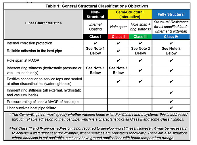
AWWA’s structural classifications subcommittee defines the criteria for Class I through IV lining systems, as summarized in Table 1, and offers technical assistance within an AWWA white paper scheduled for publication in 2019.
Table 1 provides general guidance as to the overall objective of the pressure pipeline rehabilitation and illustrates each structural classification as a sequential building block. That is, a Class II lining system exhibits the performance of both a Class I and II system; a Class III system meets Class I, II and III criteria, and Class IV meets or exceeds Class I, II, III and encompasses Class IV required functions.
Criteria
Once the performance design objectives are established for the rehabilitated pipe, the appropriate lining system should be selected based on this set criteria. The basis of design will be confirmed through type tests provided by the lining system manufacturer. Properties of the materials are then used to design the product use in specific applications, whereby the manufacture of the lining system is completed in the field (e.g. thickness of CML/PL, tube construction for CIPP, SDR of pipe for sliplining).
Dependent upon the lining system and its potential application, these may include, but are not limited to, chemical resistance, NSF/ANSI Standard 61 certification of lining systems used in potable water applications, mechanical properties (tensile, flexural and compressive), abrasion resistance, adhesion, short-term burst and HDB testing.After the selected product is properly designed, the lining system is installed. To ensure a quality system has been created, acceptance tests confirm contractual
requirements and the basis of design are satisfied. These may include: measuring applied thickness and consistency of the wall of the installed materials, adhesion, short-term mechanical properties testing from field collected representative samples, relevant hydrostatic leakage and/or pressure testing, visual/CCTV inspection throughout the entire length of the installation, and bacteriological testing may be performed.
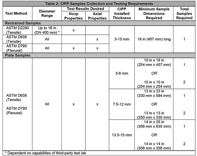
Table 2 provides a listing of resources that provide overall guidance, specific type tests for pre-project product evaluation and post-installation acceptance tests derived from the project field samples and performance of the actual lining system installed.

Lining material composition and construction, along with the manufacturing process and installation technique, vary by lining type, material manufacturer and installation technology. These differences can influence the design and overall pipe performance. As an example, a Class I CML or PL is an isotropic (or homogeneous) material, with uniform properties throughout the pipe wall. However, a Class IV fiber-reinforced CIPP system is anisotropic, with variable properties such as the hoop (radial) and axial (lengthwise along the pipe) directions. Therefore, both hoop and axial properties must be utilized to accommodate various design conditions.
These two different design classifications, and the materials and processes used to provide the respective rehabilitated pipe performance, require distinctive design protocols to ensure the quality of the pipe lining product. For these reasons, it is important to understand the chosen material in order to properly identify the means to assess and design its use in pressure pipe rehabilitation.
Whenever possible, a collection of field samples should be performed in a non-destructive manner, providing access to representative samples of the installed materials. Forexample:
- CML mortar samples can be collected onsite and delivered to the laboratory for 28-day cure and compressive testing.
- PL samples can be sprayed into a section of pipe extending from the host pipe for thickness and adhesion testing.
- CIPP samples can also be collected from a restrained extension of the host pipe or with flat panels cured inside large diameter pipe.
Testing
When collecting representative Class III or IV lining system field samples, consideration should be given to the test method requirements, sample type, material orientation, curvature of the specimen, relative location of the sample in the lining, and the sample’s thickness.
In the CIPP gravity pipe rehabilitation industry, predominantly isotropic liners have been installed for nearly 50 years. The specimen test orientation does not matter because physical properties are the same in any direction. In addition, a limited number of assurance tests were used to establish the quality of the installed CIPP. ASTM D790, flexural properties and chemical resistance testing in accordance with ASTM F1216, were the primary type and acceptance tests utilized. However, testing requirements for anisotropic, reinforced CIPP pressure pipe liners are more complex and must be carefully planned. Tensile properties are the primary type and acceptance tests for CIPP pressure pipe systems.
ASTM D2290 is a full-hoop tensile test that was developed to determine tensile properties of the restrained (full circular) ring samples and is becoming more commonly used for small-diameter CIPP pressure pipe installations. In larger-diameter installations, plate samples are still the preferred acceptance test using ASTM D638 (dog bone test) to define the designated tensile pipe performance.
As an example, Table 2 lists minimum dimensional requirements for test samples of CIPP pressure pipe in various thicknesses.
Hydrostatic pressure tests are common for the verification of a lining system used to rehabilitate pressure pipe. The purpose of the test is to locate defects in materials or workmanship and establish that the rehabilitated section being tested will not leak or leakage is within acceptable limits. ASTM F1216 provides general guidelines for hydrostatic pressure testing and suggests the testing water pressure be defined as twice the working pressure of the pipeline, or this pressure plus 50 psi, whichever is less.
This standard establishes a pressure testing acceptance criterium of 20 gallons per inch of internal pipe diameter per mile of length installed per day for the duration of the test (typically 1 hour). Care must be taken not to subject the rehabilitated pipe to test pressures that exceed the MAOP. When performing a hydrostatic test on rehabilitated pressure pipe, each individual reach of the installed lining system should be tested individually. This will minimize false readings due to trapped air and isolate any issues should they arise.
Provisions should also be made to allow the system to equalize prior to initiating the hydrostatic test, and to properly vent and drain the system after testing to eliminate vacuum and potential damage to the newly installed lining system. It is important to note that acceptance testing confirms relevant tests were selected to evaluate the process which satisfied the pipe performance requirements established in the contract documents.
Further, where additional verification may be required to determine fit-for-purpose, demonstration tests and quality assurance practices may be required. These may include, but are not limited to: utilization of computer controlled mixing systems to ensure proper resin ratio and liner saturation, data logging of applied thickness (CML/PL); cure or processing temperature monitoring and logging; and demonstration of internal service reinstatement after water main lining, post rehabilitation maintenance practices such as joining, tapping and repair of the rehabilitated pipe.
A comprehensive approach to design and testing of pressure pipe lining systems will be described in the AWWA white paper. This living document will capture the most-relevant design concepts relative to each technology group for pressure pipe rehabilitation, with the goal of integrating its content into the upcoming Fourth Edition of AWWA Manual of Water Supply Practices M28 – Rehabilitation of Water Mains. It will also offer assistance to design engineers in correctly specifying lining systems for pressure pipe rehabilitation and provide testing to assures the system owner that rehabilitation has been executed properly.
Comments