
September 2010 Vol. 65 No. 9
Features
CIGMAT Report: Update From This Unique, Industry-Specific Ongoing Research Program
The Center for Innovative Grouting Materials and Technology (CIGMAT) Research Center was established in 1994 at the University of Houston, Houston TX. CIGMAT’s goals are to foster improved understanding of grouting and coating materials under various applications. Also of interest are other competing and complementary materials and technologies to grouting and coatings used in the construction and rehabilitation of civil infrastructure and offshore pipelines.
CIGMAT is an integrated and interdisciplinary framework, drawing expertise in engineering, science and technology at the University of Houston. Over the past 15 years, CIGMAT researchers have worked on more than 50 basic and applied research projects totaling more than $6 million, which has resulted in over 120 referred journal and conference publications. Industrial members and federal/state/local agencies fund the ongoing research studies performed at the center. At present, CIGMAT is the only EPA approved national laboratory under the Environmental Technology Verification (ETV) Program to evaluate the performance of grouts, coatings, linings and many other types of repair materials for the rehabilitation of civil infrastructures. Over the years, CIGMAT researchers have developed unique testing facilities and a Life Cycle Cost model (CIGMAT-LCC) for water and wastewater systems. Every effort is made by the CIGMAT researchers to transfer technology from control studies to actual applications.
CIGMAT organizes an annual conference and exhibition in March on “Construction and Rehabilitation Activities Related to Houston & Other Major Cities” where leaders from cities and transportation operations from around the country are invited to present and discuss projects and problems related to construction and rehabilitation issues. The well-attended conference also discusses technical issues related to nondestructive testing methods, durability of materials and current construction, maintenance and rehabilitation methods related to water and wastewater systems and development of smart materials for various applications. A number of geotechnical topics related to expansive clay, rapid foundation construction and ground faulting are also discussed. The conference proceedings for the past 10 years are posted on the CIGMAT website at http://cigmat.cive.uh.edu.
Grout tests for leak control
CIGMAT has not only tested various materials for civil infrastructure and offshore pipeline applications but has developed several test protocols for testing grouting and coating materials and wastewater pipeline joints for leaks under various loading conditions.
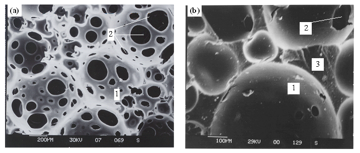
A critical issue facing the nation today involves the increased pollution found in the waterways, shorelines, rivers, bays and streams. The EPA estimates that 70 to 80 percent of this increase comes from the inflow and infiltration (I/I) of the home laterals [EPA 2000 Web site]. Several types of grout materials have been used in controlling I/I problems in wastewater systems and storm systems [Vipulanandan, 1996c]. These materials have been commonly used for leak control in below grade wet wells or holding tanks, manholes, sewer and storm lines, cracked retaining walls and other underground structures [Karol, 1990, Vipulanandan, 1996a, Vipulanandan, 2000]. CGMAT researchers investigate the grout behavior based on their microstructure using the scanning electron microscope. Figure 1 shows the microstructure of a polyurethane grout where the cell structure and the distribution and size of pores are investigated.
(1) Macro-cells (2) Macro-holes in the Macro-cell walls (3) Macro-cell walls
Fig. 1: Microstructure of a typical polyurethane grout used for rehabilitation.
Many owners are discovering that if I/I problems are not adequately controlled it will lead to frequent overflows and undue burden on the treatment facilities. The primary goal of grouting these facilities is to return the structure to its original working conditions by the oldest trenchless technology method – in situ grouting. Using grouting to control leaks in wastewater facilities and other leaking structures is one method currently being adopted. CIGMAT researchers are investigating the fundamentals of grouting leaking joints using 2D and 3D physical and numerical models [Ozgurel et al. 2005]. In Figure 2, a 2D physical model is used to investigate grouting of a leaking joint under various soil and in situ stress conditions. A typical grouted soil bulb with very low permeability that is formed around the leaking joint after grouting is shown in Figure 3. This model study also was used to quantify the advancement of the grout front based on the pumping parameters.
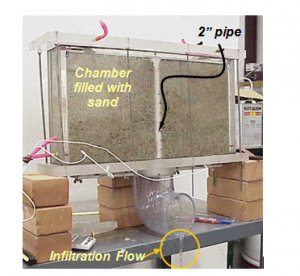
Fig. 2: 2D model test for infiltration and grouting study.
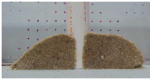
Fig. 3: Grouted soil bulb at the leaking joint.
Using a 3D model, studies were also performed to investigate the development of the grouted soil bulb around a leaking lateral joint – a typical bulb is shown in Figure 4. These model studies were critical in developing a comprehensive test protocol for grouts to rehabilitate civil infrastructures.

Fig. 4: Typical grouted soil bulb around a lateral joint.
Currently, there is no systematic method for evaluating the performance of grouts under service conditions. Hence, a testing protocol was developed to evaluate the grouts with a combination of full scale and laboratory tests for applications in the rehabilitation and new construction of wastewater facilities.
Wastewater facilities are typically wet and experience hydrostatic pressure under normal service conditions. The application of grouts to leaking joints and cracks is considered a challenge and must be evaluated. Another cause for evaluation to determine performance is the bonding between the concrete/clay brick surface and the grouting material. Chemical resistance of grouts and grout-modified materials to the sewer corrosive environment also is important.
To select the grouting material to solve the I/I problems, their performance and installation must be well understood. Restoring leaking joints and cracks in concrete structures requires considering grouted soil mass around the joints and grout behavior within leaking cracks.
The durability of a grouting material is as important as its ability to perform in its intended applications. Durability is concerned with life expectancy or endurance characteristics of the coating material. A durable grout is one that can withstand the effect of service conditions in which it is subjected; therefore, it is important to identify grouting materials for specific applications such as leak control in wastewater treatment and collection systems or other concrete structures.
Since several factors in the field can affect the performance of grouting, it is important to identify them through controlled experiments where variables are studied one at a time. In this document, a comprehensive testing program was developed to evaluate grouting for leak control applications.
The overall objective of the test protocol was to systematically evaluate grouts for infiltration control in wastewater systems and to control leaks in concrete structures. The specific objectives are: (1) to evaluate the working, mechanical and durability of grouts and grouted soils; (2) to characterize the grout-substrate interaction and durability; and (3) to verify the performance of grouted joints and repaired concrete cracks under dry and hydrostatic pressure (241 kPa (35 psi) up to 5 psi in 10 feet of water) using model tests over a period of one month.
Tests were performed using relevant ASTM and CIGMAT standards. Over 10 different grout tests were used to characterize the grouts. Several additional tests were performed with grouted soil and grout-substrate interaction. Four model tests representing various leak control configurations were also included in the test protocol.
Model tests
Based on the applications, model tests for controlling pipeline leaks and concrete repair – two schematics and the real models are shown in Fig. 5 – are proposed in the test protocol approved by the United States Environmental Protection Agency.
(http://www.nsf.org/business/water_quality_protection_center/pdf/WQPC_Grouts_Protocol.pdf).
Model Test-3 (Fig. 5a) is used to investigate the effectiveness of grouting and comparable technologies to reduce the leak at the laterals. Model Test-4 is used to evaluate the effectiveness of grouts and other technologies to reduce the leak through cracked concrete. At present, several grouts are being tested under the ETV program using the grout test protocols.
Schematic of lateral repair Model-3 test
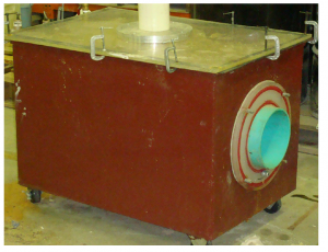
Fig. 5a: Model-3 test – lateral repair
Schematic of Model Test-4 – concrete leak repair
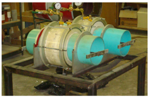
Fig. 5b: Model 4 – test for concrete repair
Coating and lining materials for corrosion control
While concrete is the most widely used construction material in large wastewater treatment plants, clay bricks have been used in manholes and old sewers. Concrete is used for below-grade wet wells or holding tanks, sewer pipelines and open-top channels. Many municipalities are discovering that certain concrete structures in wastewater treatment facilities are degrading rapidly due to acidic environment generated by bacterial activities [EPA, 1974, 1985]. There are several methods in practice to control the degradation of the concrete and clay brick wastewater facilities [Kienow et al. 1993]. The primary goal of rehabilitating these facilities is to return the structure to its original working condition using in situ methods. The addition of base materials at regular intervals is expensive especially when there is regular sewer flooding. Regularly cleaning the pipes by increasing the velocities of flow has not proved to be effective. Coating is one method currently being adopted but the effectiveness of this method for rehabilitating lift stations and sewer treatment facilities is still in question.
Sewer facilities are wet and experience hydrostatic pressure under normal service conditions. Application of coating materials to such surfaces is considered a challenge and must be evaluated [Steele, 1999]. Bonding between the concrete surface and the coating material is another key factor that must be evaluated to determine the performance of the coating. Chemical resistance of coated materials to acidic environment is also essential.
When selecting the coating systems to solve concrete corrosion problems, their performance and installation must be implicit. Restoring concrete with coatings requires considering concrete surface conditions (strength and moisture content) and the porosity of the concrete. The minimum recommended surface strength of concrete for using coatings is in the range of 1.4 to 1.75 MPa (200-250 psi) [Soebbing, 1996]. A sufficient quantity of water at the concrete surface can react with the coating material and affect the setting and the adhesion of the coating systems. The surface moisture will depend on the porosity of the concrete and hydrostatic pressure due to the water table. Coatings can debond and blister if the hydrostatic pressure exceeds the tensile adhesion of the coating material. Concrete deterioration can range from slight etching or partial loss of surface cement binder to complete loss of cement binder. Complete binder loss yields exposed coarse aggregates and reinforcing steel, which will further accelerate corrosion, cracking and spalling of the concrete.
There is limited information in the literature on the performance of coated concrete wastewater facilities and the results are not conclusive on the durability of coated materials. Several coating materials were studied by Los Angeles County and the results show that only a low percentage of coatings performed well under their testing conditions [Render et al. 1994]. Consequently, it is essential to identify good coating materials for protecting the wastewater facilities against corrosion.
Since several factors in the field can affect the performance of coating, it is vital to identify the key factors through controlled experiments where critical variables are studied one at a time. A testing program has been developed for evaluating coating materials for concrete and clay brick rehabilitation.
The objective of the coating test protocol was to evaluate the performance of coating materials for various wastewater rehabilitation projects. Specific objectives are as follows: (a) to develop a full-scale testing facility to evaluate the application and performance of coatings on a concrete surface under hydrostatic pressure; (b) to evaluate the chemical resistance of the coated concrete and clay bricks with and without holidays; and (c) to determine the bonding strength of the coating material to concrete and clay bricks.
Test plans
(i) Full Scale Test
The coatings can be applied to a dry or wet concrete surface. A dry coating condition simulates the new concrete surface while the wet condition simulated the rehabilitation. The testing program developed for evaluating coating materials are briefly discussed [Vipulanandan, 1996, 2005].
(a) Hydrostatic Pressure Test: Hydrostatic back pressure on concrete structures due to the water table was simulated by using 900 mm (36 inch) inner pipes and 1,600 mm (64 inch) outer pipes with two specially designed concrete end plates and pressurizing the annular space with water (Fig. 6). Steel frames were used to support the entire assembly. Coating the inner pipe surface represented the most difficult conditions encountered in coating structures such as lift stations. The total area available for coating was 14 square meters (150 square feet).
Wet test: The 900 mm (36 inch) concrete pipe was installed in the test chamber and pressurized at 105 kPa (15 psi) for at least two weeks before applying the coating.
Dry test: Coating was applied to new 900 mm (36 inch) diameter concrete pipe. The coated pipe was then placed in the pressure chamber for hydrostatic pressure testing.
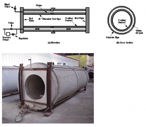
Fig. 6: Hydrostatic test configuration
(b) Measurements
Visual Inspection: The coated surfaces were visually inspected regularly and information on blistering, spalling, discoloring and cracking were noted and photographed. ASTM D 714 is used to characterize the blister size and frequency and is designated as dense, medium dense, medium or few, accordingly.
Bonding Test (CIGAMT CT-2 or modified ASTM D 4541): In situ bonding tests on the coating materials were performed at the end of the hydrostatic test. A 51 mm (2 inch) diameter core drill was used to core into the concrete surface and isolate the test area. A metal piece was glued to the coating with an epoxy. After curing for 24 hours, the bonding test was performed using a hydraulic loading system to determine the bonding strength and the type of failure.
(ii) Laboratory Tests
Chemical Resistance (CIGMAT CT-1 or modified ASTM G 20): In order to study chemical resistance, the ASTM G 20 test was modified for use with coated concrete and clay brick materials. This method is intended for use as a relatively rapid test to evaluate the acidic resistance of coated specimens under anticipated service conditions. In this test, 76 mm (3 inch) by 152 mm (6 inch) cylindrical cement concrete specimens were used. Specimens were prepared by stripping the molds from the concrete cylinders, leaving the base in place. Dry and wet cylindrical specimens were coated on all sides, except the base, and tested. For the test, two radial holes were drilled into the specimen approximately 15 mm (1/2 inch) deep.
As shown in Fig. 7 (a), the specimen was immersed in a selected test reagent to half the specimen height in a closed bottle. For coated concrete specimens changes in (1) amount of calcium leached into the in test medium (2) weight of specimen (3) appearance of specimen and (4) pulse velocity (ASTM C 597) of the specimen were measured at regular intervals. For coated clay bricks, no calcium measurement was done except in the case of cemetitious coatings. The three test reagents selected for this study are (1) deionized water (pH = 6) and (2) 1 percent sulfuric acid solution (pH = 1; representing the worst reported condition in the wastewater system). Control tests are performed with no holidays. Over 60 specimens were tested for each coating material.
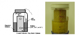
(a) Chemical test on coated material

(b) Coated samples are being tested at the CIGMAT facilities
Fig. 7: Chemical tests on coated materials with holidays
Bonding Strength: These tests are being performed to determine the bonding strength (pull-off strength) between the concrete/clay brick and the coating material over a period of time.
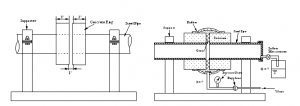
CIGMAT CT-2 or modified ASTM D 4541: In this test, a 51 mm (2 inch) diameter circular area was used for testing. Coated concrete blocks were cored using a diamond core drill to a predetermined depth to isolate the coating, and a metal fixture was glued to the isolated coating section using a rapid setting epoxy. Tests are planned for each of the coating materials over a period of several years. The test configuration is in Fig. 8.
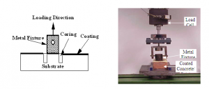
(a) Specimen preparation (b) Load frame arrangement
Fig. 8: Pull-off test method load frame arrangement
CIGMAT CT-3 or ASTM C 321: In this test, the coating was sandwiched between two rectangular concrete specimens and then tested for bonding strength. Both dry and wet concrete specimens were used to stimulate the extreme coating conditions. The bonded specimens were cured under water up to the point of testing. Tests are performed over a period of several years. The test configuration is in Fig. 9. Since sample preparation and testing in CIGMAT CT-3 (ASTM C 321) is easier, this test was selected for comparison purposes with CIGMAT CT-2.
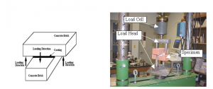
(a) Test specimen configuration (b) Load frame test setup
Fig. 9: Bonding test arrangement for sandwich test.
Pipe-joint infiltration test facility
While many small and large older cities are undergoing repairs and maintenance, several newer cities are planning to install wastewater systems. Infiltration due to leaking pipes, manholes, laterals and other components of a wastewater system will add to the problem of overflow and substantially load the treatment facilities. Frequent overflows not only lead to regulatory problems but also increase treatment cost. Leaking systems will result in the erosion of soils through the leaking joints leading to the settlement of the ground surface, formation of sinkholes and damage to surrounding pavements and structures. Erosion of soil materials around the pipes and manholes can lead to formation of void and settlement of pipes, accelerating the damage. Eroding soils entering the wastewater system through the leaking joints can cause problems within the wastewater system.
Literature review clearly indicates that each type of pipe is tested differently in determining the infiltration rate at the pipe joint. Therefore a testing method must be developed to better quantify the infiltration at pipe joints under various joint-loading conditions. Based on literature review and ASTM testing standards, a testing protocol to determine infiltration at the pipe joint must be developed.
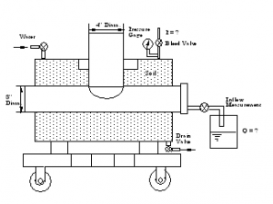
The primary purpose of the test protocol was to establish a comprehensive procedure for testing pipe joints for infiltration. The model tests will verify the performance of the joints up to an applied external hydrostatic pressure of 48 kPa (7 psi) (Figure 10).
A test protocol was developed to test the pipe joint under the following conditions:
a. Straight joint (Method A)
b. Angular deflection (Method B)
c. Shear load (Method C)
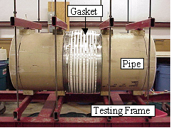
Fig. 10: Configuration of a pipe-joint infiltration test
The CIGMAT Research Center provides manufacturers the testing facilities to test pipe joints. To date, CIGMAT researchers have tested clay, concrete, Hobas pipe and PVC pipe joints. For more information about the testing facilities, contact CIGMAT at cigmat.cive.uh.edu.
About the author:
C. Vipulanadan, PhD, P.E., is a chairman and professor at the University of Houston, and director of CIGMAT and the Texas Hurricane Center for Innovative Technology (THC-IT) (cigmat.cive.uh.edu). The CIGMAT research center is a joint university-industry consortium.
References
Annual Book of ASTM Standards (1995), Vol. 06.01, Paints-Tests for Formulated Products and Applied Coatings, ASTM, Philadelphia, PA.
Annual Book of ASTM Standards (1995), Vol. 04.05, Chemical Resistant Materials; Vitrified Clay, Concrete, Fiber-Cement Products; Mortar; Masonry, ASTM, Philadelphia, PA.
EPA (1974), “Sulfide Control in Sanitary Sewerage System”, EPA 625/1-74-005, Cincinnati, OH.
EPA (1985), “Odor and Corrosion Control in Sanitary Sewerage System and Treatment Plants”, EPA 625/1-85/018, Cincinnati, OH.
Karol, R. H. (1990), Chemical Grouting, Marcel Dekker Inc., New York, NY, p. 465
Kienow, K. and Cecil Allen, H. (1993). “Concrete Pipe for Sanitary Sewers Corrosion Protection Update,” Proceedings, Pipeline Infrastructure II, ASCE, pp. 229-250.
Kulkarni, S. P. and Vipulanandan, C. (2006) “Hot Wire Method to Characterize the Thermal Conductivity of Particle-filled Polymer Grouts Used in Pipe-in-Pipe Application,” Journal of Testing and Evaluation, ASTM, Vol. 34, No. 3, pp.224-232, 2006.
Liu, J. and Vipulanandan, C., (2005) “Bonding Strength of Epoxy Coatings used to protect Concrete in Wastewater Facilities and 3-D FEM Analyses”, Proceedings, Pipelines 2005, ASCE, Houston, TX, pp. 827-837.
Liu, J., and Vipulanandan, C. (2005) “Tensile Bonding Strength of Epoxy Coatings to Concrete Substrate,” Cement and Concrete Research, Vol. 35, pp.1412-1419, 2005.
Liu, J., and Vipulanandan, C. (2004) “Long-term Performance of Epoxy Coated Clay Bricks in Sulfuric Acid,” Journal of Materials in Engineering, ASCE, Vol. 16, No. 4, pp.349-355, 2004.
Mebarkia, S., and Vipulanandan, C. (1999) “Mechanical properties and water diffusion in polyester polymer concrete”, Journal of Engineering Mechanics 121 (12) (1999) 1359-1365.
Ozgurel, G., Gonzalez, H. A. and Vipulanandan, C., (2005) “Two dimensional Model Study on Infiltration Control at a lateral Pipe Joint using Acrylamide Grout”, Proceedings, Pipelines 2005, ASCE, Houston, TX, pp. 631-642.
Redner, J.A., Randolph, P. Hsi, and Edward Esfandi (1992), “Evaluation of Protective Coatings for Concrete” County Sanitation District of Los Angeles County, Whittier, CA.
Redner, J.A., Randolph, P. Hsi, and Edward Esfandi (1994), “Evaluating Coatings for Concrete in Wastewater facilities: Update,” Journal of Protective Coatings and Linings, December 1994, pp. 50-61.
Soebbing, J. B., Skabo, Michel, H. E., Guthikonda, G. and Sharaf, A.H. (1996), “Rehabilitating Water and Wastewater Treatment Plants,” Journal of Protective Coatings and Linings, May 1996, pp. 54-64.
Steele, J. and Steele, J. (1999), ‘Performance Criteria for Coatings on Concrete in Chemical Exposures”, Journal of Protective Coatings and Linings, July1999, pp. 29-35.
Vipulanandan, C., Ponnekanti, H., Umrigar, D. N. and Kidder, A. D. (1996a) “Coating Materials for Watewater Facilities,” Proceedings, Materials for New Millennium, ASCE , pp. 850-860, 1996.
Vipulanandan, C., Jasti, V., Magill, D. and Mack, D. (1996b), “Shrinkage Control in Acrylamide Grouts and Grouted Sands,” Proceedings, Materials for the New Millennium, ASCE, Washington D.C., pp.840-850.
Vipulanandan, C. and Jasti, V. (1996c), Characterization of Polymer and Cellular Cement Grouts for Sewer Rehabilitation, Research Report No. CIGMAT/UH 96-3, University of Houston, Houston, TX.
Vipulanandan, C. and Neelam Kumar, M. (2000), “Properties of Fly Ash-Cement Cellular Grouts for Sliplining and Backfililng Applications,” Proceedings, Advances in Grouting and Ground Modification, ASCE, GSP 104, Denver, CO, pp. 200-214.
Vipulanandan, C. and Liu, J. (2005a) “Performance of Polyurethane-Coated Concrete in Sewer Environment,” Cement and Concrete Research, Vol. 35, pp.1754-1763.
Vipulanandan, C., and Liu. J. (2005b) “Sewer-Pipe Joint Infiltration Test Protocol Developed by CIGMAT “, Proceedings, Pipelines 2005, ASCE, Houston, TX, pp. 553-563, August 2005.
Vipulanandan, C., and Pasari, G. (2005c) “Life cycle Cost Model (LCC-CIGMAT) for Wastewater Systems”, Proceedings, Pipelines 2005, ASCE, Houston, TX, pp. 740-751.
Vipulanandan, C., and Kulkarni, S. P. (2007) “Shear Bonding and Thermal Properties of Particle-Filled Polymer Grout for Pipe-in-Pipe Application,” Journal of Materials in Civil Engineering, Vol. 19, No. 7, pp.583-590.

Comments