
January 2010 Vol. 65 No. 1
Features
ASCE Manual of Practice No. 118 For Belowground Pipeline Networks For Utility Cables
There are basically three modes of construction for “outside plant” facilities for communications and electric power supply lines. These include:
1. Aerial/overhead plant in which the cables are individually suspended between utility poles placed on the order of 100 – 300 feet apart;
2. Belowground plant consisting of an array of parallel conduit paths, typically four to 6-inch diameter pipe, spanning the distance between relatively large manholes, separated by distances on the order of 500 to 1,000 feet; and
3. Belowground plant installed by directly burying the cables within the soil, including cable along a road, highway or street, or service drops to the home.
All three modes have been commonly used in the industry, with an increasing amount of belowground facilities being placed relative to aerial plant in more recent decades, primarily driven by regulations. Due to the significantly different characteristics of the two belowground methods, mode two has been specifically designated as “underground (conduit) plant” to distinguish this method from mode three comprising individual “direct-buried” cables. Although the terminology suggests that there is a clear distinction between the mode two (underground conduit system) and mode three (direct-buried cables) methods of construction, in practice there have been variations in each category that tend to blur the differences.
In support of belowground installations, including the encouragement of innovative designs and methods for enhancing the deployment and utilization of such pipelines, the American Society of Civil Engineers (ASCE) has recently published the ASCE Manuals and Reports on Engineering Practice No. 118 for Belowground Pipeline Networks for Utility Cables — commonly referred to as “MOP No. 118”, as shown in Figure 1. The effort was sponsored by the U.S. Department of Transportation and the FHWA Turner-Fairbank Highway Research Center.
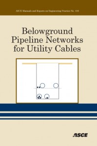
Figure 1 ASCE Manual of Practice No. 118
(Reprinted with permission from ASCE)
The objective of the manual, or guide, is to present a brief description of present and past practices for the placement of utility cables belowground, including conventional underground conduit systems and direct-buried methods, as well as more recent techniques in which individual pipes or ducts may be advantageously deployed in conjunction with “direct-buried” cables. Related design, construction and operational requirements and guidelines are also provided, as well as a brief description of various methods and technologies for placing cables into the conduits. In addition, specific design and implementation information is provided for a cost-effective, space efficient hybrid joint-use system for utility cables that provides many advantages relative to previous or existing methods of belowground construction.
The manual is divided into six main sections, consistent with the sequence in this article.
Underground conduit systems
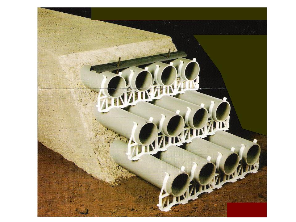
The extensive conduit facilities of underground plant (mode two) are appropriate for limited applications, such as associated with the trunk or feeder portions of the traditional telecommunications network, due to the high cost of this method of construction. The construction of the conduit networks is material and labor-intensive, and requires significant manhole real estate, but does provide flexibility, including the capability to postpone installation of expensive trunk or feeder facilities (fiber-optic) until the need arises. Such underground conduit systems are also the only viable alternative in metropolitan or large urban areas where overhead lines and/or future digging are not an option. Figure 2 illustrates typical underground conduit construction.
Section 2 of MOP No. 118 provides a description of underground conduit systems including the basic components (conduits, structures and accessories) and design and construction requirements. Information is provided in the following categories:
Safety-Based Requirements (National Electrical Safety Code)
o Location and position;
o Excavation and backfill;
o Ducts and joints; and
o Manholes, handholes and vaults.
Design and Construction Guidelines
o Conduit sizing;
o Section lengths;
o Conduit type (PVC, HDPE); and
o Construction.
Operation and Maintenance
o Conduits (accessories); and
o Manholes (work rules).
Issues
o Cost (facilities, maintenance); and
o Safety.
Direct-buried systems
In contrast to underground conduit systems, direct-buried plant (mode three) represents a relatively low cost method for placing individual cables belowground between any desired terminations, but loses flexibility with respect to future additions or replacements. (Figure 3 illustrates typical direct-buried construction.) Indeed, the inherent lack of such upgradeability has been a primary factor in inhibiting the desired widespread deployment of new wireline telecommunications technologies, based upon the use of fiber-optic cables, in established areas and communities with buried facilities. Conversely, existing communities served by aerial distribution plant (mode one) have been ready candidates for such upgrades. Similarly, energy-hungry consumers and industries continue to push the limit of existing power lines which need to be replaced or supplemented. Thus, in addition to the relatively low cost to install and maintain aerial facilities, flexibility represents another reason for the continuing deployment of aerial lines.
The current trends for buried construction across much of the country introduce potentially serious problems when upgrades and maintenance are inevitably required in the future. In such cases, digging in established areas is typically required, often accompanied by damage to public and private property, including roads, and associated traffic problems. Furthermore, there are safety problems corresponding to digging in an area with existing utilities (electric power, gas). Even when proper procedures (One-Call notification, identification, utility location, manual exposure) are followed, accidents can occur, resulting in property damage and personal injury, possibly death. The use of “trenchless technology,” including horizontal directional drilling (HDD), following proper procedures, does reduce the degree and likelihood of such problems, but does not eliminate them, and typically has a significant cost penalty. Thus, while current trends in the widespread use of buried construction are desirable, there is an urgent need to modify present construction practices to avoid unfortunate future problems, including significant safety issues.
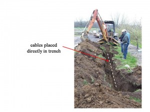
Figure 3 Typical Direct-Buried Construction
Such innovative methods have been developed under the sponsorship of the U.S. Department of Transportation, for which detailed information is provided in the manual, as discussed below.
There are several general methods currently available for the “direct-burial” of cables, as well as individual relatively small ducts (e.g., one to 2-inches):
• Trenching;
• Plowing; and
• Boring (e.g., piercing tools, horizontal directional drilling).
Section 3 of MOP No. 118 describes the equipment and procedures employed for each of these categories. In general, information is provided based on safety requirements of the National Electrical Safety Code (NESC), as well as construction practices provided by the Rural Utilities Service and the communications industry (e.g., Telcordia Technologies). In particular, there are requirements and recommendations for:
• Cable properties;
• Handling;
• Depth of cover;
• Physical separation;
• Routing; and
• Trench conditions.
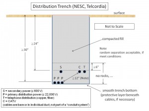
Figure 4 illustrates a typical set of the trench requirements.
Figure 4 Basic Requirements for Direct-Buried Distribution Cable Trench
(Reprinted with permission of the ASCE)
Cable installation methods in duct (subhed)
Section 4 of MOP No. 118 describes three basic methods for placing utility cables within ducts that have previously been installed in the field:
- Pulling;
- Pushing; and
- Blown-cable.
All three methods have been successfully applied in industry, and each has its advantages, limitations, and range of application. The methods continue to evolve, with innovations based upon the cable characteristics and newly introduced products. Some techniques and equipment combine elements of these categories.
The most direct method for installing a cable within a duct is to connect a rope or pull-line to the leading end of the cable, using an appropriate type of grip, and to then pull the cable into the path. Mechanized equipment is often required since the pulling force may be significant. The force imposes a tensile load on the cable, which must not exceed its allowable tensile capability. The major disadvantage relates to possible placement distances. The tension or pull force at the leading end of the cable is required to offset the frictional drag forces that accumulate along the length of the cable. For the simple case of a cable resting on the bottom of a straight duct path, as illustrated in Figure 5, the frictional drag is essentially due to the weight of the cable in combination with the coefficient of friction at the cable-duct interface, which in many cases appears to be relatively low.
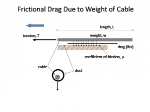
Figure 5 Basic Cable Pulling Mechanism (Straight Path)
(Courtesy of Outside Plant Consulting Services, Inc.)
In practice, however, route curvature at discrete bends as well as cumulative curvature due to seemingly minor deviations from a nominally “straight” path lead, result in rapidly escalating tension. This is known as the “capstan effect,” illustrated in Figure 6, and results in increased frictional drag forces due to increased bearing pressure caused by tension pulling the cable snugly against the inside of curved portions. Such effects greatly limit practical pulling distances.
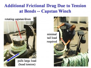
Figure 6 Illustration of Capstan Effect
(Courtesy of Outside Plant Consulting Services, Inc.)
Cable pushers represent an alternative to pulling equipment and have the advantage of avoiding the need for a pull line. In principle, placement distances are limited by similar frictional effects as described above, including an analogous capstan effect due to increased bearing pressure caused by an axial compressive force pushing the cable snugly against the outside of curved portions. Unlike the tensile load on a cable, which is generally characterized by industry specified or reasonably well-defined limits, allowable axial compressive loads on cables are less well-defined. A typical failure mode of cables under axial compression comprises buckling and kinking, and is a function of the magnitude of the required push force, the bending stiffness of the cable, and the clearance in the duct.
In comparison to the familiar pulling or pushing methods, innovative “blown-cable” techniques have recently been developed. These methods utilize high pressure air introduced at the cable feed end of the duct which provides a forward thrust on the cable. In the “low-air-speed” alternative, a piston is connected to the leading end of the cable to apply a pull force, supplemented by a pushing force at the cable feed end. In the “high air-speed” method (Figure 7), the piston is omitted and the air is allowed to rush out the far end of the duct, resulting in a viscous drag force applied to the outer surface of the cable. The distributed nature of the latter force avoids the tension buildup associated with the capstan effect, resulting in placement distances relatively insensitive to route bends and curvature. The system also includes an essential cable pusher, which is advantageously employed to provide even greater placement distances. The original application for the blown-cable techniques was light-weight fiber-optic cables, but the equipment has been successfully utilized for the installation of other type cables, albeit typically at shorter placement distances.
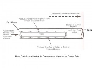
Figure 7 High Air-Speed Blown-Cable Principle of Operation
(Courtesy of Outside Plant Consulting Services, Inc.)
Hybrid belowground cable networks
Section 5 of the manual provides specific design and implementation rules for a hybrid cost-effective, space efficient joint-trenching system for utility cables combining the advantages of direct-buried and underground conduit construction methods. Such Belowground Cable Network (BCN) systems are intended to represent cost-effective, space-efficient overall solutions for direct-buried utility (electric power, telephone, and CATV) or miscellaneous communication lines. These systems provide an opportunity for conveniently and safely accomplishing cable upgrades, at a relatively low initial incremental cost to the utilities and/or their customers, as well as resulting in long-term savings on a life cycle basis. Although Section 5 focuses on one type of such a network, as illustrated in Figure 8, other designs or architectures may possibly be developed to accomplish similar objectives.
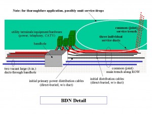
Figure 8 Example BCN Architecture
(Courtesy of Outside Plant Consulting Services, Inc.)
An important feature of the BCN is the use of cost-effective joint (shared) construction practices, consistent with optimized utility practices. Thus, a single main trench along the right-of-way would be used for several utilities or organizations, as well as a single service trench to each home (or small business) for residential type applications, as appropriate. The size and type of the indicated initially installed (direct-buried) distribution cables would be selected based upon the conventional engineering rules used by the utilities, in their initial attempt to meet present and future (ultimate) anticipated needs. The BCN upgrade capability would only be used to meet unanticipated needs that nonetheless often arise, due to the desire to introduce new technologies, increase capacities and/or replace degraded cables and wires.
Two initially vacant, relatively large diameter (e.g., four to 6-inch) main duct paths would be routed along the right-of-way (ROW), in the same main trench as the direct-buried distribution cables, but otherwise have no initial connections to the terminals, equipment or hardware. One duct could, for example, be used for future electric power upgrades or maintenance, and the other duct for communications (telephone and/or CATV), although the actual final implementation may vary, based upon the actual needs. The present architecture comprising only two main ducts is based upon the probability that not all utilities would require an upgrade in the foreseeable future, and that such duct capacity would be sufficient for practical cable upgrade or replacement needs.
A flush mounted handhole is an essential element in this example BCN. The BCN employs a joint-use (shared) handhole to serve the needs of all participating utilities or organizations. For residential (or small business) applications, a handhole may be co-located with each group of above-ground service pedestal terminals. For non-residential applications (highways, thoroughfares), the handholes would be located adjacent to required equipment or terminals or other convenient locations; e.g., to facilitate cable installation and/or accomplish a splice.
BCN – status
The incorporation of a belowground cable network, such as described above, into the design standards or procedures of road authorities would necessarily only occur over an extended period of time. MOP No. 118 represents an important item in the support of such a trend. Another essential element in the ability to encourage the implementation of a BCN, or equivalent, is the successful demonstration of its practical application in a variety of construction projects. In this regard, several related field trials have been successfully accomplished at the time of the writing of this article:
- Arlington, TX: Mitchell Street (600 feet); South Davis Drive (1,600 feet)
- Monroe, NC: NC State Road 1223 (720 feet)
In addition, a 400-foot segment is planned for installation, parallel to U.S. Highway No. 1, in the city of Danvers, MA.
In particular, the manual provides details regarding the two installations in Arlington, TX, within property controlled by the University of Texas at Arlington (UTA). In this case, the BCN networks were installed within the grassy strips, adjacent to sidewalks, on Mitchell Street and on South Davis Drive, intersecting streets within the campus. The objective was to provide UTA with a convenient network for the future installation of communications cables to serve local university facilities.
Due to the anticipated surface damage, and potentially large restoration expenses, it was decided that trenchless methods should be considered for installing the BCN along both streets. This construction procedure therefore differs from that implied in the description of the BCN in which it is assumed that an open trench would be available to conveniently place the various cables and BCN conduits and handholes. Nonetheless, such an environment (established community or area) is frequently encountered and it is important to verify that the BCN could, in fact, be deployed in such an application.
Mini-HDD equipment was utilized to cost-effectively place two 4-inch field-fused PVC conduits, along both routes. Although there were several challenges in utilizing a mini-HDD rig to simultaneously pullback the two conduits, as well as to properly interface with the total of six handholes, the installations were successfully and efficiently accomplished. Figure 9 shows the conduits at one of the handhole locations, prior to placement of the handhole itself. Figure 10 shows a completed installation. Additional details are provided in MOP No. 118.
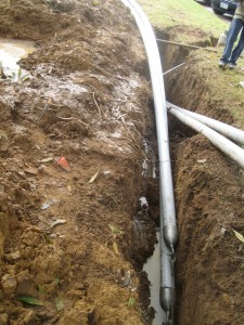
Figure 9 Overlapping Conduits from Adjacent Pullbacks
Although the UTA trials did not include the placement of any direct-buried cables, any initially required utility cables, or preferably small ducts for their later containment, may be installed simultaneously alongside the two BDN conduits during the mini-HDD pullback operation, or possibly placed within one of the latter BDN ducts.
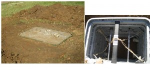
Figure 10 Installed Handhole (With and Without Cover), Mitchell Street
Summary
ASCE Manuals and Reports on Engineering Practice No. 118 for Belowground Pipeline Networks for Utility Cables address the use of pipes (conduits) for the placement of utility cables, including communications and electric power lines. This manual supplements other MOPS produced by the ASCE Pipeline Division, such as those dedicated to trenchless construction. In particular, MOP No. 118 provides background information and design requirement for the placement of cable ducts comprising a formal underground conduit system, as well as cables, or individual ducts for cables, directly buried in the soil. Various technologies for subsequent placement of cables within the installed conduits is also provided, including the theoretical principles governing the techniques.
In addition, a belowground cable network is presented that combines the advantages of underground conduit systems with that of direct-buried construction, and represents a cost-effective system that provides a degree of upgrade capability. This feature supports the desired trend towards belowground cable installation, reducing the hazards associated with aboveground utility poles, and helping avoid damage to other utilities and roads and highways. The results of several field applications of the BCN are described. The development effort for the MOP was sponsored by the U.S. Department of Transportation and the FHWA Turner-Fairbank Highway Research Center.
Although the National Electrical Safety Code attempts to add clarification, the use of duct, or innerduct”, in such “direct-buried applications sometimes tends to blur the distinction between “direct-buried” and “underground conduit” construction.
ABOUT THE AUTHORS:
Dr. Lawrence M. Slavin, Outside Plant Consulting Services Inc., (973) 983-0813, fax (973) 983-0813, email lslavin@ieee.org; Dr. Oleh Kinash, IUPUI-Purdue School of Engineering & Technology, (317) 278-1957, fax (317) 278-0785, okinash@iupui.edu; Dr. Mohammad Najafi, the University of Texas at Arlington, (817) 272-0507, fax (817) 272-2630, email najafi@uta.edu.
Comments